

close
Choose Your Site
Global
Social Media
Views: 0 Author: Site Editor Publish Time: 2026-10-26 Origin: Site


In industrial fluid management and commercial fire safety, operational uncertainty is a significant risk factor. Imagine a facility manager navigating a noisy, dimly lit mechanical room during a sudden pressure drop alarm. In such high-stakes environments, they need to know instantly whether water or critical fluid is flowing through the pipeline. Relying on assumptions can lead to catastrophic system failures or severe safety breaches. This operational necessity introduces the OS&Y valve—Outside Screw and Yoke—which serves as the established industry standard for piping systems requiring immediate, foolproof visual confirmation of flow status.
Looking at current industry trends, there is a massive shift toward smart building automation and IoT sensor integration across commercial infrastructure. However, regulatory bodies and safety engineers continue to emphasize a critical point. Digital sensors cannot replace physical, mechanical fail-safes. The core concept of this valve type rests on a golden rule of mechanical design. The physical position of the threaded stem directly dictates and displays the internal status of the equipment. Consequently, this physical design perfectly complements modern electronic monitoring, creating an uncompromised safety loop.
This comprehensive guide explains how to easily identify the operational status, explores the mechanical principles behind these components, discusses optimal installation orientations, and provides objective criteria for selecting the right valve infrastructure for your project.
Visual Confirmation: The fundamental rule of thumb for operators is straightforward. The valve is open if the threaded stem is visibly raised above the handwheel mechanism.
Design Advantage: The outside screw and yoke design isolates the stem threads from the internal fluid medium. This isolation prevents internal corrosion and thread damage.
Primary Applications: Regulatory codes mandate these specific valves in numerous fire protection and sprinkler systems because their operational status can be verified from a distance.
Maintenance & Sourcing: Because the stem is exposed to the external environment, routine lubrication is essential. Procurement should focus on reputable manufacturers offering robust hardware solutions.
To make informed decisions regarding pipeline infrastructure, you must understand the fundamental mechanics of the equipment. Engineers utilize this specific type of linear motion valve primarily to permit or completely halt the flow of fluid within a pipe.
The acronym OS&Y stands for Outside Screw and Yoke. This terminology directly describes the physical construction of the unit. The screw refers to the threaded stem that controls the internal gate. Meanwhile, the yoke is the sturdy bracket structure holding the handwheel in place. Specifically, both the threaded mechanism and the yoke are positioned entirely outside the main valve body. Therefore, the operational threads never touch the water, chemicals, or gases flowing through the pipeline. This external placement is a critical engineering choice designed to prevent internal corrosion and mechanical seizing.
The operational mechanism of a rising stem gate valve relies on the seamless interaction between the handwheel, the yoke nut, and the threaded stem. When an operator turns the handwheel counterclockwise, the handwheel itself does not move upward or downward. It remains at a fixed elevation on the yoke. Instead, the turning motion rotates an internal yoke nut. This nut engages with the threads of the stem, forcing the stem to travel linearly upward. As the stem rises, it pulls the internal gate—often a solid or flexible wedge—out of the fluid pathway. In contrast, turning the handwheel clockwise forces the stem downward, pushing the wedge back into the valve seat to create a watertight seal. For automated industrial setups, durable pneumatic versions integrate heavy-duty pneumatic cylinders to drive this stem up and down, offering precise control while maintaining the same reliable rising stem principles.
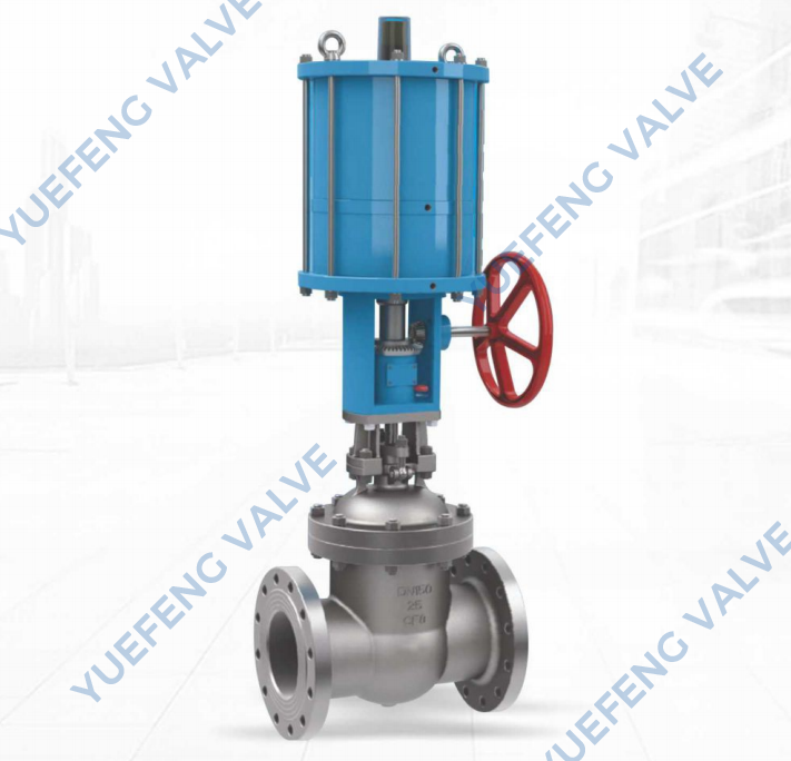
The primary advantage of this design is the complete elimination of guesswork regarding the operational state of the pipeline. Understanding how to visually read the equipment is a fundamental requirement for facility maintenance and safety compliance.
Visual verification is immediate and requires no specialized tools. You can confidently confirm that the pipeline is open if the threaded stem protrudes prominently above the handwheel. The length of the exposed stem directly corresponds to the internal position of the gate. When fully open, the maximum length of the threaded stem is visible above the center of the handwheel. This physical protrusion serves as an unmistakable indicator that the internal wedge has been lifted clear of the fluid path, allowing unobstructed flow. Facility inspectors rely heavily on this visual cue to effortlessly verify the gate valve open and closed position from across a crowded mechanical room.
Conversely, identifying a closed pipeline is equally straightforward. When the operator turns the handwheel to shut off the flow, the stem retracts downward through the yoke nut. In the fully closed state, the top of the threaded stem sits flush—or very nearly flush—with the top of the handwheel. If there are no exposed threads visible above the wheel, the internal gate is fully seated. The fluid flow is completely blocked. This binary visual system ensures that status checks can be conducted rapidly and accurately during emergency sweeps.
The integration of these valves into fire protection infrastructure is not merely a preference. It is often a strict regulatory requirement dictated by international safety organizations. Fire marshals and safety inspectors mandate these specific components because they mitigate the severe risk of a false open scenario.
In emergency situations, a non-indicating valve might appear open when it is actually closed, potentially starving a sprinkler system of water during an active fire. The rising stem design provides empirical, visual proof of the water supply status. Furthermore, modern fire safety protocols require continuous monitoring. These valves are uniquely suited for the installation of electronic tamper switches mounted directly onto the yoke. If an unauthorized individual attempts to rotate the handwheel and close the valve, the downward movement of the stem triggers the tamper switch. This action immediately sends a supervisory alarm signal to the central fire control panel, creating a dual-layer defense against system failure.
A common technical inquiry during pipeline design involves the spatial orientation of the hardware. While these units are versatile, their physical positioning significantly impacts long-term reliability and maintenance requirements.
Engineering best practices strongly dictate that you should install the valve in a vertical orientation, with the stem pointing straight up. While horizontal installation—where the stem points sideways—is mechanically possible and sometimes necessary due to tight spatial constraints, it is generally considered a suboptimal configuration for long-term durability. Gravity naturally assists in keeping the seating area clear when installed vertically.
Installing the equipment with the stem pointing horizontally or downwards introduces specific mechanical risks. Gravity causes suspended solids, sediment, and debris within the fluid to settle. In a horizontal or inverted installation, this debris can easily accumulate in the gate track or the bonnet cavity. Over time, this stubborn buildup prevents the wedge from seating properly. Ultimately, this leads to slow leaks and an inability to achieve a complete, bubble-tight shutoff.
When specifying valves for a commercial or industrial project, engineers typically evaluate the rising stem design against the Non-Rising Stem alternative. Both serve the same fundamental purpose, but their structural differences dictate their ideal applications.
Feature | OS&Y (Outside Screw & Yoke) | NRS (Non-Rising Stem) |
|---|---|---|
Visual Flow Indication | Immediate and obvious. Stem is up means open. | Requires external indicator or physical testing. |
Space Requirements | High overhead clearance needed for rising stem. | Compact footprint. Ideal for tight spaces. |
Thread Location | Outside the valve body. Isolated from fluid. | Inside the valve body. Submerged in fluid. |
Corrosion Risk to Threads | Low. Protected from harsh process fluids. | High. Vulnerable to particulates and chemicals. |
Best Application | Fire protection, critical industrial lines. | Underground utilities, cramped mechanical rooms. |
Furthermore, thread exposure is a critical factor. Since the Non-Rising Stem threads are located inside the valve body, they are constantly submerged in the process fluid. This makes them highly prone to corrosion if the fluid contains particulates or harsh chemicals. In contrast, the external yoke design completely isolates the threads in a cleaner environment, drastically reducing internal wear.
To ensure the longevity and reliability of your pipeline infrastructure, implementing a standardized maintenance schedule is critical. While these units are exceptionally robust, their external mechanisms require specific attention. Imagine a maintenance worker conducting a routine check during a shutdown, only to find a handwheel completely seized. Regular upkeep prevents these costly delays.
Lubrication: Because the threaded stem is exposed to the ambient environment, it is susceptible to accumulating dust, dirt, and industrial grime. Over time, this particulate matter can harden, making the handwheel incredibly difficult to turn. Maintenance personnel should routinely clean the exposed threads with a wire brush and apply a high-quality, industrial-grade grease.
Packing Gland Checks: If moisture or fluid begins to weep from the area where the stem exits the valve body, the packing material may be compromised. You can typically resolve this issue by carefully tightening the packing gland nuts. It is vital to tighten these nuts incrementally and evenly to avoid binding the stem.
Regular Cycling: Valves that remain in a static position for years are prone to seizing due to internal scale buildup or oxidation. Industry standards strongly recommend exercising the valve—fully closing and then fully opening it—at least once every quarter to ensure the mechanical components remain functional and responsive.
The operational integrity of any fluid management or fire protection system is directly dependent on the quality of its components. When procuring infrastructure for critical applications, it is imperative to source materials from established manufacturers that adhere to rigorous international testing and certification standards. Inferior metallurgy or imprecise machining can lead to premature failure, leaking, or disastrous system blowouts under high pressure.
For modern industrial applications, integrating advanced automated solutions can significantly enhance operational efficiency. Facility managers looking to upgrade their systems should consider implementing durable pneumatic configurations. These setups offer robust automated control—utilizing high-strength ductile iron bodies and precision-machined wedges—while maintaining the reliability expected of heavy-duty industrial equipment.
When planning your next infrastructure project, we encourage procurement teams to explore diverse configurations to find the precise specifications required for the operational environment. Selecting certified, high-grade OS&Y gate valve hardware ensures regulatory compliance, minimizes long-term maintenance costs, and guarantees the safety of the facility.
The rising stem gate valve remains an essential, non-negotiable component for system visibility and industrial safety. By ensuring that your operational staff understands the golden rule—the pipeline is open if the stem is up—you significantly reduce the risk of catastrophic operational errors. This simple, brilliant mechanical design ensures clear operational status from a distance.
Whether you are managing a complex commercial fire protection network or a standard fluid piping system, choosing the right hardware is a smart investment in long-term reliability. It improves overall system safety and makes routine maintenance significantly easier. We encourage you to evaluate your current infrastructure and explore high-quality upgrades. Visit GWV Valve at https://www.gwvvalve.com to discover durable pneumatic and manual valving solutions tailored to your next demanding piping project.
It stands for Outside Screw and Yoke. This terminology refers to the external threaded stem, known as the screw, and the sturdy structural bracket, known as the yoke, that holds the handwheel outside the main pressure-containing valve body.
Simply look at the external threaded stem. If the stem is raised prominently above the handwheel, the fluid path is open. If the stem is retracted and sits flush with the wheel, the pipeline is completely closed.
No. Like all gate-style valves, they are specifically designed to be either fully open or fully closed. Using them to throttle or regulate flow causes severe turbulence, leading to vibration and permanent damage to the internal wedge.
This common issue is usually due to a lack of proper lubrication on the external threads or overtightened packing nuts. Thoroughly cleaning the exposed threads with a wire brush and applying fresh industrial grease usually resolves the stiffness immediately.
Yes. National and international fire codes frequently mandate their use in fire suppression systems. Fire marshals require them because their visual open/closed status prevents the catastrophic error of leaving a water supply line accidentally closed during a fire emergency.
Industry best practices recommend a visual inspection monthly to ensure no leaks or tampering has occurred. Additionally, maintenance teams should exercise the valve—fully closing and opening it—at least quarterly to prevent the internal wedge from seizing due to scale buildup.


