

close
Choose Your Site
Global
Social Media
Views: 0 Author: Site Editor Publish Time: 2026-10-09 Origin: Site


Gate valves serve as the undisputed workhorses of industrial piping networks. They rely on a precise synergy of internal components to function effectively. Yet, pipelines still leak. Procurement managers sometimes source the wrong equipment for critical refinery projects. Why does this happen? The root cause often traces back to a fundamental misunderstanding of internal architecture. Ignoring these mechanical nuances triggers costly unplanned downtime. It creates severe on-site safety hazards. It can even lead to catastrophic environmental leaks.
This comprehensive guide serves as the ultimate resource for engineers, maintenance crews, and purchasing agents. We will dissect the anatomy of these essential isolation valves. You will learn how core elements operate and how to proactively maintain them. More importantly, we will outline specific criteria to evaluate when specifying equipment for demanding industrial applications.
The Foundation: The pressure-retaining shell protects internal mechanisms. It safely contains volatile fluid media.
The Flow Control: The internal wedge and stationary seats act as the core shut-off mechanism. They rely on precise machining to create a bubble-tight seal.
The Actuation: The stem and stuffing box assembly translate rotational motion into linear movement. This prevents hazardous fugitive emissions.
Maintenance is Key: Routine inspection of sealing materials and proper thread lubrication extend equipment lifecycle.
Material Matters: Choosing the right metallurgy depends strictly on operating pressure, temperature, and media characteristics.
At its core, this equipment is a linear motion isolation device. Its primary job is to start or completely stop fluid flow. Control valves modulate or throttle flow rates. Isolation units, however, must remain either fully open or fully closed. When fully retracted, the internal obstruction disappears from the flow path. This results in minimal pressure drop and high fluid efficiency.
To understand how robust units maintain pipeline integrity under extreme pressures, we must examine the component breakdown. The anatomy consists of six primary mechanical assemblies. These include the body, the bonnet, the wedge, the seat, the stem, and the packing. Each piece withstands specific mechanical stresses, shear forces, and thermal fluctuations.
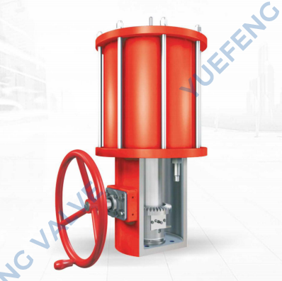
The structural integrity of any industrial piping component begins with its exterior housing. Together, the gate valve body and bonnet create the primary pressure boundary. This robust shell must be thick and durable. It handles the maximum allowable working pressure of the system without warping or fracturing.
Serving as the primary pressure vessel, the body is the largest single part of the assembly. It houses the internal mechanisms. It also provides vital connection points to the broader piping network. Depending on pipeline specifications, the body connects via flanged ends, threaded connections, or heavy-duty welded ends.
From a fluid dynamics perspective, the internal cavity is meticulously cast or forged. This ensures a straight-through flow path. Such specific geometry minimizes turbulence when the line is fully open. Furthermore, the upper cavity is sized to fully accommodate the retracted disc. This guarantees it does not obstruct high-velocity media flow. For example, durable pneumatic series often utilize WCB carbon steel or CF8M stainless steel bodies. These materials easily handle pressures from PN16 up to PN64 in demanding environments.
Acting as the secure cover for the main housing, the bonnet completes the pressure-retaining boundary. It houses the actuation shaft and sealing assembly. By unbolting or unscrewing this cover, maintenance personnel gain direct access to the internal cavity. This allows for rapid inspection, repair, or part replacement. The attachment method dictates suitability for different industrial environments.
Bolted designs are the most prevalent for heavy industrial applications. High-strength studs compress a gasket between the flanges. This provides reliable sealing while allowing straightforward field disassembly. Screwed-in designs typically serve smaller, lower-pressure utility lines. Welded covers are engineered for hazardous chemical or high-pressure steam lines where zero external leakage is mandatory. Pressure seal designs cater specifically to extreme high-pressure environments above ASME Class 900. Internal line pressure forces the cover against a specialized seal ring. Consequently, higher internal pressure creates a tighter seal.
While the outer shell safely contains the pressure, internal flow control elements dictate the primary function of the equipment. The gate valve wedge and seat are the most critical components for achieving a flawless, bubble-tight shut-off. Their physical interaction must be exact. Even microscopic scoring or debris can lead to internal leakage, commonly known in the field as passing.
The wedge is the physical barrier that lowers into the flow stream to block the media. Industrial processes involve wildly varying temperatures and pressures. Therefore, manufacturers produce these barriers in several distinct designs to accommodate physical expansion and contraction.
Wedge Type | Design Characteristics | Best Application Scenarios |
|---|---|---|
Solid Wedge | Single-piece solid metal construction. Highly robust and simple. | General water, oil, and gas lines with stable temperatures. |
Flexible Wedge | Features a machined perimeter groove for slight flexibility. | High-temperature steam lines. Actively prevents thermal binding. |
Split Wedge | Two separate disk halves pushed outward by an internal spring mechanism. | Systems with extreme temperature gradients requiring self-alignment. |
Seats are the stationary sealing surfaces located inside the main cavity. When an operator closes the line, the descending disc presses firmly against these angled faces to arrest the flow. The precision of the angle between the two faces must perfectly match the angle of the descending barrier.
These sealing surfaces fall into two primary configurations. Integral seats are machined directly into the base material of the housing. This eliminates a potential leak path. However, repairing a worn integral face requires specialized in-line machining equipment. In contrast, renewable seats are separate rings pressed, threaded, or welded into place. Heavy industry heavily favors renewable rings. If abrasive media scores the surface, maintenance teams can swap out the individual ring without discarding the entire heavy metal casting.
An operator’s input must be reliably transferred to the internal flow control elements. This applies whether the force comes manually via a handwheel or automatically via a pneumatic actuator. This mechanical transfer is handled by the gate valve stem and packing assembly. It is a critical subsystem that also prevents hazardous media from escaping into the atmosphere.
The stem is a precision-machined threaded shaft. It possesses high tensile strength to pull the disc out of the flow stream. It also requires high compressive strength to force the disc into the sealing faces.
Rising stem configurations place the threads outside the pressurized cavity. As the handwheel turns, the shaft rises upward. This provides a clear, immediate visual indication of the open or closed status. Because the threads remain external, they are isolated from corrosive process media. Maintenance teams can easily lubricate them. Non-rising stem designs feature a shaft threaded at its lower end. It screws directly into the internal disc. The shaft rotates in place but does not move vertically. This design proves highly advantageous in environments with restricted vertical clearance, such as underground water mains.
Fluid leakage risks are highest where the moving shaft exits the pressurized housing. The stuffing box seals this vulnerable area. Packing rings are inserted into this machined chamber. These rings are often manufactured from braided graphite for high temperatures or PTFE for corrosive chemicals.
A packing gland compresses the material tightly against the moving shaft via gland nuts. Proper compression is vital. Too loose, and fugitive emissions escape, posing severe environmental risks. Too tight, and excessive friction restricts movement. This makes operation exceptionally difficult and accelerates wear on mechanical assemblies.
Reliable operation is a testament to mechanical synergy. A step-by-step breakdown reveals how these parts interact continuously during a standard cycle.
When an operator turns the handwheel counterclockwise to open the line, rotational energy transfers to the stem nut. In a rising stem design, this pulls the threaded shaft upward. The shaft lifts the barrier linearly off the stationary faces. As the barrier ascends into the upper cavity, fluid flows freely with minimal resistance.
Closing the line reverses the process. The shaft drives the barrier downward until its angled faces make firm, wedging contact with matching angles on the stationary rings. Throughout this dynamic process, compressed graphite or PTFE maintains a dynamic seal around the moving shaft. Meanwhile, the bolted exterior safely contains internal pressure. If pipeline debris scores the metal face, or if graphite loses elasticity, the entire system's integrity is compromised.
The industrial valve sector is undergoing a massive transformation. Driven by stringent environmental regulations like API 624 and EPA mandates, we are witnessing an industry-wide pivot. Facilities are rapidly adopting low-emission packing materials. These advanced die-formed graphite sets are designed to virtually eliminate fugitive emissions.
In addition, the push for operational efficiency has accelerated the adoption of automated actuation. Pneumatic control systems are replacing manual handwheels in critical refinery and chemical processing nodes. This shift allows for rapid, remote isolation during emergency shutdown scenarios. Advanced metallurgy is also trending upward. While carbon steel remains the petrochemical backbone, duplex stainless steels are dominating severe service applications. Applying Stellite overlays to seating surfaces is now standard practice. Plant managers realize they are not just buying a piece of metal; they are investing in long-term lifecycle reliability.
Specifying the right equipment prevents premature failure. Field engineers must evaluate three core parameters before procurement.
First, assess the media characteristics. Abrasive slurries require hardened seating surfaces, while highly corrosive acids demand CF8M stainless steel bodies and PTFE packing. Second, evaluate the pressure and temperature profile. High-pressure steam applications strictly require flexible wedges to prevent thermal binding. Finally, consider the actuation requirements. If the installation site lacks vertical clearance, a non-rising stem is mandatory. For automated process control, integrating a durable pneumatic actuator ensures reliable, fast-acting isolation without manual intervention.
Proactive maintenance programs are essential for ensuring industrial safety. They help facilities avoid unplanned pipeline shutdowns. Understanding how to troubleshoot individual mechanical assemblies allows maintenance teams to resolve minor issues before they escalate.
Fixing Stem Leaks: Weepage along the actuation shaft is the most common field issue. Relaxation of sealing rings over time typically causes this. A careful, even quarter-turn of the gland nuts can re-compress the graphite rings. This halts the leak without requiring a full system shutdown. Extreme caution must be exercised, however, as over-tightening will bind the shaft.
Addressing Seating Issues: Failure to shut off completely is frequently due to welding slag, scale, or debris trapped between sealing faces. Forcing the handwheel closed with a cheater bar will permanently score the precision-machined metal. Instead, slightly open the line. Allow high-velocity fluid to flush the debris away, then attempt to close it again. If surfaces are permanently damaged, they must be repaired through lapping.
Lubrication and Proactive Care: For outside screw and yoke configurations, exposed external threads must be kept free of environmental grit. Regularly lubricate them with industrial-grade grease. This simple act reduces friction on the drive nut and prevents thread degradation.
Every component within an isolation valve plays an indispensable role. The heavy-duty exterior shell provides critical pressure containment. The internal flow control elements deliver a precise, bubble-tight seal. A practical understanding of these mechanical assemblies empowers procurement managers to make informed, application-specific purchasing decisions.
Furthermore, this knowledge equips maintenance teams to troubleshoot leaks and perform preventative care. Prioritizing high-quality materials and rigorous maintenance schedules maximizes equipment lifespan. It safeguards operations against costly downtime. If you are planning your next critical piping project, consult with experienced valve engineers to ensure your specifications perfectly match your operational demands. Explore high-performance solutions at GWV Valve to find the exact durable, automated, or manual configuration your facility requires today.
Every component is essential for safe operation. However, the internal disc and stationary rings are the most critical for actually stopping fluid flow. The exterior housing and upper cover are fundamentally responsible for pressure containment and structural safety.
A rising stem moves upward vertically when the line is opened. This provides a clear visual indicator of the equipment's open or closed status. A non-rising stem simply rotates in place without moving up or down. This makes it the ideal choice for tight spaces with limited vertical clearance, such as underground vaults.
Minor fugitive emissions can often be resolved by slightly and evenly tightening the gland nuts. This re-compresses the sealing material inside the stuffing box. If the gland is fully bottomed out or the material has degraded completely, the line must be safely isolated and depressurized. The old rings can then be extracted and replaced with a fresh set.
Yes. In many industrial designs, maintenance personnel can unbolt and remove the upper cover to access the internal cavity. This allows them to extract the disc and replace renewable seat rings while the main housing remains securely welded or bolted in the pipeline. This process is known as in-line maintenance.
Gate valves are designed strictly for isolation, meaning they must be fully open or fully closed to prevent damage to the internal disc. Globe valves feature a different internal baffle design that allows them to effectively throttle and regulate flow rates without sustaining severe erosion.
For rising stem configurations, the position is visually obvious. If the threaded shaft protrudes high above the handwheel, the line is open. If it is flush with the wheel, the line is closed. For non-rising stem designs, operators must rely on external position indicators or physically test the handwheel's resistance.


