

close
Choose Your Site
Global
Social Media
Views: 0 Author: Site Editor Publish Time: 2026-10-13 Origin: Site


If you spend enough time managing industrial piping systems, you quickly learn that pipeline leaks are rarely random. They are almost always the result of component fatigue or improper specification. While quarter-turn flow control devices are celebrated for their compact footprint, their reliability is never guaranteed by default. It is the direct result of precise engineering and material selection. When internal mechanisms fail, they trigger costly system downtime, ruin production batches, and create severe environmental hazards. This guide breaks down the essential anatomy of these systems, helping you master the interplay between the structural housing, the flow-control element, the rotational shaft, and the internal barrier to ensure long-term operational integrity.
Anatomy Overview: A standard industrial flow-control unit consists of four primary mechanical components. These include the robust outer body, the central dynamic element, the rotational shaft, and the internal compliant lining.
The Core Mechanism: The butterfly valve disc acts as the primary flow-control gate. Engineers deploy concentric, double-offset, and triple-offset designs to handle varying pressure drops and extreme temperature requirements.
Mechanical Synergy: The butterfly valve stem and seat work together in a highly engineered relationship. They anchor the central element, transmit rotational torque from the actuator, and provide the primary barrier against internal fluid bypass.
Advanced Barriers: An engineered butterfly valve sealing structure utilizing industrial-grade materials like EPDM, PTFE, or hardened metal alloys is absolutely essential for achieving zero-leakage performance under high stress.
Customization Matters: Selecting the correct materials for these core elements extends the operational lifespan of the pipeline and significantly reduces long-term maintenance budgets.
At its core, quarter-turn flow control is a masterclass in mechanical efficiency. By rotating a central plate exactly 90 degrees, the system transitions seamlessly from a wide-open state to a complete, bubble-tight seal. However, behind this seemingly simple operation lies a complex assembly engineered to withstand extreme thermal fluctuations and mechanical shearing forces. Whether you are operating manual hand levers on a water line or high-precision automated pneumatic units in a chemical plant, the seamless interaction of these parts dictates the overall safety of your infrastructure.
Understanding this anatomy is far more than an academic exercise. For facility managers, piping engineers, and procurement teams, it is a practical necessity. Deep knowledge of these parts allows for rapid troubleshooting of unexpected fugitive emissions. It also enables the precise specification of replacement parts, preventing catastrophic blowouts before they compromise an entire facility.
The fluid control sector is currently undergoing a massive shift toward smarter, lower-emission technologies. Driven by stringent environmental regulations regarding fugitive emissions, engineers are moving away from basic elastomeric linings toward advanced composite materials and multi-layered metal barriers. Furthermore, there is a distinct industry preference for low-friction geometries. By minimizing the physical rubbing between internal components during the opening and closing cycles, modern designs drastically reduce the torque required to operate them. This trend not only extends the lifecycle of the unit but also allows facilities to downsize their pneumatic and electric actuators, leading to significant energy savings and lower initial capital expenditures.
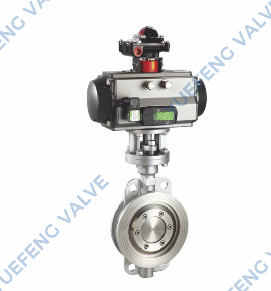
The outer housing acts as the structural bedrock of the entire assembly. It serves as the primary pressure-retaining boundary, housing all internal flow-control hardware. This heavy-duty casing must fit securely between pipe flanges and effectively absorb the mechanical vibrations and thermal expansion characteristic of active industrial piping systems. If this outer shell lacks the necessary structural rigidity, it will inevitably deform under pipeline pressure, leading to a critical compromise in the internal barriers.
Manufacturers engineer several housing styles to suit specific installation requirements. The wafer style is characterized by a lightweight, compact profile without protruding lugs, designed to be sandwiched tightly between pipe flanges. It remains the go-to choice for cost-effective, space-constrained applications. In contrast, the lug style features threaded inserts cast directly into the perimeter. By allowing the unit to be bolted independently to each flange, it supports end-of-line service. This enables downstream pipe maintenance without requiring a complete upstream system drain. For maximum structural support in large-diameter, high-pressure environments, flanged styles feature integral flanges on both faces.
Functioning as the gatekeeper of your pipeline, this dynamic element directly restricts or regulates fluid passage. Its hydrodynamic profile is a primary determinant of the flow coefficient Cv and the overall pressure drop characteristics. Beyond its physical shape, the offset design is the single most critical engineering factor dictating how this component interacts with the internal lining.
Engineers generally categorize these designs into three distinct tiers based on performance needs. Concentric or zero offset designs feature a shaft that aligns perfectly with the centerlines of both the pipeline and the housing. This is an economical solution for low-pressure liquid handling where constant rubbing is acceptable. Specifically for more demanding applications, double offset high performance designs shift the shaft away from both centerlines. This allows the plate to lift away from the lining almost immediately upon opening, drastically reducing frictional wear. For elite applications, triple offset configurations add a third, conical geometry. The metal plate contacts the barrier only at the precise fraction of a second of closure, eliminating rubbing entirely and enabling a bubble-tight seal even in extreme superheated steam applications.
The rotational shaft functions as the critical link between the external actuator and the internal flow gate. It transmits the massive rotational torque required to combat fluid pressure. Modern industrial designs prioritize safety through blowout-proof mechanisms, utilizing specialized retaining rings to prevent shaft ejection during sudden pressure surges. To ensure true longevity, the interaction between these parts must be engineered to minimize torque requirements while maintaining perfect alignment.
Simultaneously, the internal compliant lining provides the final closure seal. Because the shaft must pass directly through this lining to connect to the central plate, this interface is highly vulnerable to leakage. To solve this engineering challenge, manufacturers integrate heavy-duty packing glands to create a secondary barrier, shielding the external environment from internal pipeline pressure. For standard HVAC or municipal water treatment, EPDM or PTFE Teflon materials are preferred for their flexibility. Conversely, high-pressure steam and abrasive slurry lines absolutely necessitate the use of hardened metal alloys to resist melting or physical degradation.
The overall integrity of your processing system depends heavily on how well the internal barrier holds up under continuous cycling. In practice, when the unit enters the closed position, the outer circumference of the plate compresses forcefully against the lining. This mechanical interference creates a tight barrier that stops fluid migration, measured strictly against rigorous industrial leakage standards. To maintain this performance, a multi-tiered approach is deployed. Primary sealing occurs at the main interface, while secondary seals at the shaft interface prevent dangerous fugitive emissions.
Material Type | Temperature Range | Best Applications | Durability Profile |
|---|---|---|---|
EPDM Rubber | Up to 120°C | Water, HVAC, Mild Chemicals | High flexibility, excellent tear resistance, low cost. |
PTFE Teflon | Up to 200°C | Aggressive Acids, Food Grade Processing | Superior chemical inertness, lower friction coefficient. |
Laminated Metal | Up to 600°C+ | High-Pressure Steam, Abrasive Slurries | Zero elastomeric degradation, fire-safe design, highly rigid. |
Industry innovation is currently focused heavily on reducing mechanical friction. By utilizing specialized geometries, modern manufacturers offer low-friction pneumatic series that drastically lower the torque required by the actuator. This advancement saves compressed air energy and extends the lifecycle of the elastomeric barrier by preventing premature tearing during high-speed, repeated cycling. Furthermore, today's high-performance units often offer bidirectional shutoff, ensuring your pipeline remains completely secure regardless of unexpected changes in flow direction.
The control interface is just as vital as the mechanical hardware itself. For smaller-diameter lines where infrequent adjustment is the norm, manual hand levers provide a straightforward, tactile control method. However, when line pressure creates significant resistance, manual gearboxes become necessary. They offer the mechanical advantage required for an operator to close large-diameter lines without physical strain.
In highly automated facilities, pneumatic and electric actuators are the industry standard. Pneumatic systems are heavily favored in safety-critical, fail-safe scenarios because they can be configured with spring-return mechanisms to snap shut instantaneously upon power loss. Electric actuators, on the other hand, offer the precise modulation required for advanced SCADA-integrated control systems. Regardless of the power source, the connection point—often a keyed or square shaft—must be perfectly matched to the mounting pad to eliminate mechanical play and ensure highly consistent performance.
Selecting the right hardware is a strict exercise in balancing performance requirements with material limitations. Procurement engineering teams must move beyond simple pricing models and conduct a thorough analysis of their specific environment. To ensure a proper specification, evaluate the following criteria:
Media Chemistry: Is the fluid corrosive, abrasive, or completely neutral? Abrasive slurries will destroy standard rubber within weeks, requiring hardened alloys instead.
Thermal Extremes: Does the process experience sudden temperature spikes? Standard elastomers fail above 120 degrees Celsius, pushing the requirement toward PTFE or metal barriers.
Pressure Dynamics: Are there frequent water hammer effects or pressure surges? High-pressure lines demand double or triple offset designs to prevent the central plate from jamming into the lining.
Actuation Speed: Does the system require emergency shutdown capabilities? If so, low-friction pneumatic setups are mandatory for sub-second closure times.
Once these exact parameters are defined, matching components becomes a straightforward engineering task. When in doubt, consulting with specialized manufacturers ensures that the internal configurations—from the shaft alloy to the specific barrier compound—are perfectly aligned with your site safety standards.
Even the most robust industrial hardware requires a proactive maintenance philosophy. Early detection of component fatigue is the defining difference between a scheduled, simple repair and a catastrophic emergency shutdown. Common red flags include fluid bypassing the closed plate, which typically points to severe degradation of the internal lining. Alternatively, moisture dripping from the top shaft indicates a failure of the packing glands or secondary O-rings. If a manually operated unit feels excessively stiff or requires a cheater bar to turn, it is actively signaling a build-up of internal debris or severe shaft corrosion.
To maximize service life, engineers should implement a regular cycling schedule. Even for units that remain statically open or closed for months, stroking them partially every few weeks prevents the rubber lining from permanently adhering to the metal plate. When a failure finally occurs, always perform a cost-benefit analysis before discarding the entire heavy metal housing. In many high-performance models, installing an OEM soft-seal replacement kit can restore the unit to factory-new condition at a mere fraction of the cost of total pipeline replacement.
Quarter-turn flow control devices are highly engineered assets, not just simple pipe fittings. The outer housing, dynamic plate, rotational shaft, and internal barrier must function in perfect harmony to ensure the safety, efficiency, and environmental compliance of your facility. By investing in high-quality components tailored strictly to your process media, and by maintaining a rigorous inspection schedule, you minimize costly downtime and protect your infrastructure from operational risks.
We highly encourage facility operators and piping engineers to continually explore the latest advancements in sealing technology and automated actuation. By selecting the exact right configuration—whether it is a specialized low-friction pneumatic series for high-speed automated control or a robust triple-offset design for extreme high-pressure service—you optimize your process control for decades to come. Evaluate your current pipeline demands and explore advanced, high-quality valve solutions to find the perfect engineered fit for your specific industrial challenges.
While every component provides necessary structural integrity, the central dynamic plate and the internal compliant lining are generally considered the most vital. Their precise physical interaction is the primary factor that defines the ability to halt fluid flow completely and prevent dangerous internal bypass leaks under pressure.
Yes. In many industrial designs, particularly those featuring two-piece housings or high-performance offset configurations, the primary linings and shaft seals are fully replaceable. Installing a new soft seal kit can often restore the equipment to factory-new performance without the costly need to cut the entire housing out of the pipeline.
External shaft leakage is a classic, undeniable sign that the secondary barrier structure—typically the packing glands or internal O-rings—has failed. This failure is usually the result of long-term mechanical friction, natural elastomer aging, or aggressive chemical degradation. It indicates that an immediate seal replacement is required to ensure plant safety.
A concentric design places the shaft exactly in the center of the pipeline bore, causing the plate to remain in constant, rubbing contact with the lining throughout the entire 90-degree rotation. An offset design shifts the shaft away from the centerline, creating a cam-like motion. This allows the plate to lift away from the lining instantly upon opening, significantly reducing friction, wear, and required operating torque.
Your choice must be dictated strictly by the process media temperature, pressure, and chemical properties. EPDM rubber is an excellent, cost-effective choice for standard municipal water services. PTFE Teflon offers superior chemical resistance for harsher acidic environments. Solid laminated metal is strictly necessary in high-temperature steam or highly abrasive applications where elastomeric materials would instantly melt or tear.
The lifespan varies wildly based on application conditions. In standard clean water applications operating at ambient temperatures, a high-quality EPDM lining can easily last 10 to 15 years. However, in highly abrasive slurry lines or environments with frequent pressure spikes and high-speed cycling, elastomeric linings may require replacement every 12 to 24 months. Upgrading to advanced low-friction geometries can significantly extend this baseline lifespan.
The most common cause of sudden, catastrophic failure is improper material specification for the process media, specifically resulting in chemical degradation or thermal melting of the internal lining. Another frequent cause is water hammer—a sudden pressure surge that can physically bend the rotational shaft or permanently deform the central plate, instantly destroying the tight mechanical seal.


