
Views: 0 Author: Site Editor Publish Time: 2026-07-27 Origin: Site


Fluid system design involves incredibly high stakes. Uncontrolled reverse flow can lead to catastrophic pump failure. It also causes dangerous cross-contamination and severe system downtime. We rely heavily on the Check Valve as a critical safeguard in these complex piping networks. This component offers passive protection for various industrial applications. The underlying concept often seems deceptively simple to engineers. Yet, specifying the wrong component quickly creates severe maintenance bottlenecks. These errors routinely cause destructive water hammer and mechanical chatter. This guide breaks down the core types of check valves. It explains their specific operational mechanics in clear detail. We provide an evidence-based framework for specifying the right component. You will learn how to match valves to your requirements. We cover fluid dynamics, pressure limits, and compliance rules thoroughly. By the end, you will know exactly how to protect your systems.
Passive Protection: Check valves operate entirely on system pressure (cracking pressure) without external actuation, making accurate system profiling critical.
Application Dictates Type: There is no universal check valve; selections must balance flow capacity (Cv) against the physical state of the media (e.g., slurries vs. high-purity gases).
Orientation Constraints: Installation parameters (vertical vs. horizontal flow) instantly rule out certain valve architectures (like standard swing valves in downward vertical flow).
Total Cost of Ownership: Oversizing or undersizing leads to valve chatter, premature wear, and costly water hammer effects.
You must understand basic fluid dynamics to appreciate valve functionality. They rely entirely on forward fluid velocity to open. Upstream pressure pushes against the internal mechanism. Once the force exceeds the internal resistance, fluid passes through. When forward flow decreases, gravity or back-pressure forces them closed. They require zero external power or manual actuation. This makes them highly reliable safety devices.
Engineers often confuse cracking pressure and reseal pressure. Cracking pressure is the minimum upstream force required to open the valve initially. It represents the exact moment fluid breaks the internal seal. Reseal pressure acts differently. It is the specific pressure drop required to shut the valve tightly. A realistic tolerance gap exists between these two metrics. They rarely align perfectly. A valve might open at 2 PSI but require a 5 PSI back-pressure to achieve a bubble-tight seal. Failing to account for this gap causes systemic leakage.
We generally classify them as "normally closed" devices. They remain shut by default until system energy forces them open. You should view them strictly as one-way directional safety barriers. Do not use them as throttling devices. They cannot regulate flow rates precisely. Using a Check Valve for flow control guarantees premature mechanical failure.
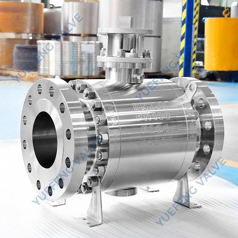
Selecting the correct architecture prevents long-term operational headaches. We categorize them by their internal mechanical structures. Each design offers specific trade-offs regarding flow capacity, closing speed, and maintenance requirements.
A hinged disc swings open when fluid flows forward. It swings out of the fluid path, allowing maximum flow capacity. The disc drops back onto the seat when flow stops.
Best Uses: High-volume, low-velocity applications like municipal water and wastewater transport.
Limitations: They are highly prone to water hammer. Mounting orientation remains strictly limited. You cannot use them in downward vertical flow lines because gravity prevents closure.
A guided piston or poppet lifts upward off a seat. System pressure drives this vertical movement directly.
Best Uses: High-pressure systems handle these valves beautifully. Compressible media like steam, air, and process gases work perfectly here.
Limitations: Tight internal tolerances cause distinct vulnerabilities. Debris quickly fouls the mechanism. The piston jams easily if particles enter the guide track.
A compressed spring assists the closing mechanism constantly. It forces the disc shut just before zero flow occurs.
Best Uses: They excel at mitigating destructive water hammer. You can install them in versatile orientations. Both horizontal and vertical layouts accept spring-loaded designs safely.
Limitations: The spring introduces a higher pressure drop compared to swing models. It requires continuous energy to keep the valve open.
Two semi-circular plates pivot on a central, spring-loaded hinge. They fold together during forward flow and snap shut upon reversal.
Best Uses: Space-constrained piping layouts benefit immensely. They offer lightweight structural requirements. You save significant installation space between pipe flanges.
Limitations: Maintenance procedures remain highly complex. You cannot repair them easily inline. Technicians must remove the entire unit for basic service.
A free-floating or spring-assisted ball seats against a precisely machined ring. Forward flow pushes the ball off the seat.
Best Uses: Viscous media and thick slurries flow easily through them. Systems prone to heavy particulate buildup rely on them heavily. The ball rotates naturally, providing a unique self-cleaning effect.
Limitations: They generate noticeable noise if system pressure fluctuates rapidly.
Engineers deploy these components to solve very specific fluid routing problems. We rely on them to protect expensive downstream equipment and ensure strict environmental compliance.
Pump and Compressor Protection: Sudden power failures cause fluid to reverse direction instantly. This backflow spins pump impellers backward rapidly. It destroys expensive internal bearings. A strategically placed Check Valve prevents reverse rotation entirely. It protects downstream compressors from sudden, destructive pressure surges.
Backflow Prevention & Compliance: Municipal water systems face strict cross-connection control regulations. Sanitary environments demand absolute separation between potable water and contaminated fluids. These valves satisfy critical health and safety compliance standards. They ensure dirty water never flows back into clean public supplies.
Maintaining Prime in Suction Lines: Centrifugal pumps cannot pump air. They require fluid in the suction line to start. Foot valves act as specialized check valves submerged in the source fluid. They keep the suction line filled when the pump shuts off. This eliminates manual priming delays.
Mixed Media Isolation: Complex manifolds often blend multiple gases or liquids. Operators must prevent dangerous cross-media contamination. Directional valves isolate individual supply lines securely. They ensure high-pressure gases do not force their way into low-pressure chemical tanks.
Treating these devices as simple commodities guarantees system failure. We recommend utilizing the STAMPED methodology. This industry-standard framework forces engineers to evaluate Size, Temperature, Application, Media, Pressure, Ends, and Delivery systematically.
You must assess cracking pressure requirements against acceptable pressure drops. Flow coefficient (Cv) defines how much fluid passes through at a specific pressure drop. Avoid the dangerous trap of matching valve size to pipe size directly. You must calculate actual flow velocity. An oversized unit will fail just as quickly as an undersized one.
Chemical compatibility dictates material choice entirely. You must match the body and elastomer seals to the fluid properties.
Material Category |
Common Elastomer Seals |
Ideal Industrial Applications |
|---|---|---|
Stainless Steel (316) |
PTFE, FKM |
Highly corrosive chemicals, sanitary food lines. |
Brass / Bronze |
Buna-N, EPDM |
Potable water, low-pressure compressed air. |
PVC / CPVC |
Viton, EPDM |
Wastewater processing, aggressive acid handling. |
Exotic Alloys (Hastelloy) |
Metal-to-Metal |
Extreme high-temperature steam, harsh petrochemicals. |
Orientation aggressively screens out incompatible architectures. You must define horizontal, vertical-up, or vertical-down flow paths early. A standard swing mechanism functions flawlessly in horizontal lines. It fails completely in downward vertical flows. Always confirm gravity assists the closing mechanism rather than hindering it.
Industrial applications require documented proof of safety. Note necessary industry approvals before purchasing. Look for API standards in oil and gas environments. Rely on ASME codes for boiler and pressure vessels. NSF certification remains mandatory for potable water applications. FDA compliance is strictly required for sanitary food and pharmaceutical lines.
Even perfectly specified components fail if installed poorly. You must anticipate operational risks and plan for inevitable maintenance cycles.
Selecting a device with excessively high flow capacity destroys it rapidly. If the actual system velocity cannot hold the internal mechanism open, it bounces. This rapid opening and closing is called chatter. Chatter pulverizes internal hinges and springs. It leads directly to premature mechanical failure. You avoid this by calculating exact flow velocities during design.
Delayed closure in non-spring-loaded designs exacerbates shockwaves. When fluid reverses before the disc seats, it slams shut violently. This creates massive hydraulic shock. The resulting pressure spike travels through the piping network at the speed of sound. It risks immediate pipe rupture and bracket failure.
Engineers often falsely assume the fluid remains perfectly clean. Real-world systems contain pipe scale, rust, and particulate matter. You must discuss the necessity of upstream strainers. Lift and spring-loaded types require strainers to prevent seating failure. Debris trapped on the seat guarantees continuous leakage.
Leave at least five pipe diameters of straight run upstream of the unit.
Install a Y-strainer before any lift-style mechanism.
Verify the directional flow arrow stamped on the body twice before tightening bolts.
Matching internal diameter purely based on existing pipe size.
Ignoring the manufacturer's published minimum flow velocity requirements.
Failing to account for elastomer degradation under high operating temperatures.
Consider the labor costs of future repairs. Compare inline repairability against required system shutdowns. Top-entry swing models allow mechanics to replace internals while the body remains piped. Wafer styles require complete removal. You must drain the line and spread the flanges apart. This drastically increases maintenance downtime.
Navigating manufacturer catalogs requires organized data. You must translate your operational needs into precise technical specifications.
Prepare comprehensive data before requesting any quotes. Provide exact minimum and maximum flow rates. State the normal operating temperatures and extreme peak temperatures. Define the specific gravity and viscosity of the media clearly. This data prevents vendors from guessing your requirements.
Do not accept generic marketing sheets. Look for vendors providing transparent, detailed flow curves. They should supply documented cracking pressure tolerances upon request. Reliable material traceability certificates remain essential for compliant systems. If a manufacturer cannot provide a Cv chart, find a different supplier.
Do not attempt complex system sizing alone. We encourage you to consult directly with a fluid system engineer. Submit your detailed P&ID (Piping and Instrumentation Diagram) parameters to a specialist. A customized specification review ensures you purchase the exact component required for safe, long-term operation.
Check valve selection always represents a delicate balancing act. You must balance maximum flow efficiency against reliable, rapid closure. We have explored the structural differences between swing, lift, and spring-loaded architectures. We outlined the critical importance of calculating accurate flow velocities to prevent chatter. Remember to evaluate your media compatibility carefully. Proper elastomer selection prevents dangerous chemical leaks. Emphasize that treating these components as cheap commodities invites disaster. They are highly engineered, system-critical safety devices. Cutting corners here leads directly to disproportionate maintenance costs and severe facility safety risks.
A: Installing it backward completely blocks forward flow. The system fluid hits the closed disc immediately. This creates massive upstream pressure spikes. Pumps suffer dead-heading and can burn out quickly. Piping joints may rupture under the sudden stress. Always verify the directional flow arrow stamped on the body before installation.
A: Cracking pressure is the minimum upstream force required to open the device initially. It merely breaks the internal seal. Pressure drop represents the kinetic energy lost as fluid travels through the fully open unit. High cracking pressure does not always equal high pressure drop. Calculate both metrics carefully.
A: No. We cannot use them as primary isolation or manual shut-off valves. They do not guarantee 100% zero-leakage under all operating conditions. Debris or low back-pressure often prevents a bubble-tight seal. Always install dedicated manual isolation valves alongside them to ensure safe maintenance procedures.
A: Chatter usually indicates an oversized unit. The system flow velocity cannot keep the internal mechanism fully open. It repeatedly bounces against the internal seat. You must calculate the actual flow coefficient rather than matching pipe size. Replacing the oversized unit with a smaller one typically resolves vibration completely.


