

close
Choose Your Site
Global
Social Media
Views: 0 Author: Site Editor Publish Time: 2026-10-02 Origin: Site


Fluid systems demand robust protection against reverse flow. Unchecked backflow ruins expensive pumps and compromises operational safety. Every facility manager knows these high stakes. However, many engineers select these critical components based merely on pipe size. This common error often leads to premature mechanical failure. You might experience devastating water hammer events. You could face massive, unexpected pressure drops. We designed this comprehensive guide to solve these exact issues. We provide a clear, engineering-aligned framework for evaluating your options. You will learn how fluid dynamics and media types dictate proper selection. We also explore how installation constraints influence your final mechanical choice. Proper specification guarantees long-term system integrity. It prevents dangerous contamination and keeps your processes running smoothly. Read on to discover how to shortlist the right equipment. You will gain actionable insights to improve reliability. Let us help you eliminate unexpected downtime across your industrial fluid networks.
Type dictates function: Valve selection (e.g., swing vs. spring-assisted) fundamentally alters pressure drop and water hammer mitigation.
Sizing over-rules pipe diameter: Check valves must be sized for flow rate, not line size, to prevent premature wear and "chatter."
Cracking pressure is the baseline: Understanding minimum upstream pressure requirements is non-negotiable for system efficiency.
Orientation matters: Not all check valves function in vertical piping; gravity and flow direction dictate mechanical viability.
Every fluid network faces the constant threat of reverse flow. Selecting the right Check Valve serves as your primary defense mechanism. System integrity depends entirely on this crucial barrier. Precise selection defines your primary success criterion. You must prevent backflow continuously. Reverse flow can destroy expensive centrifugal pumps instantly. It cross-contaminates delicate media batches. It can also drain pressurized systems unexpectedly.
Poor specification carries heavy operational consequences. Choosing the wrong mechanical design triggers cascading failures. You will face increased maintenance downtime. Your facility will suffer energy losses through excessive pressure drops. Pumps must work harder to push fluid through restrictive components. You also risk catastrophic failure from severe water hammer. Fast-closing applications require specific internal mechanisms. Using a slow-closing model here guarantees pipeline damage.
Compliance baselines dictate stringent safety requirements. Your selection must satisfy industry-specific standards. Regulatory bodies do not tolerate improper installations. You must adhere to established codes for safety and liability. We recommend strictly following these major engineering frameworks:
API 594: Governs flangeless, wafer, and double-door designs for petroleum applications.
ASME B16.34: Establishes strict pressure and temperature ratings across various materials.
AWWA Standards: Dictates acceptable performance for municipal water and wastewater systems.
Meeting these standards ensures operational longevity. It protects your personnel from hazardous blowouts. It also shields your organization from severe compliance liabilities.
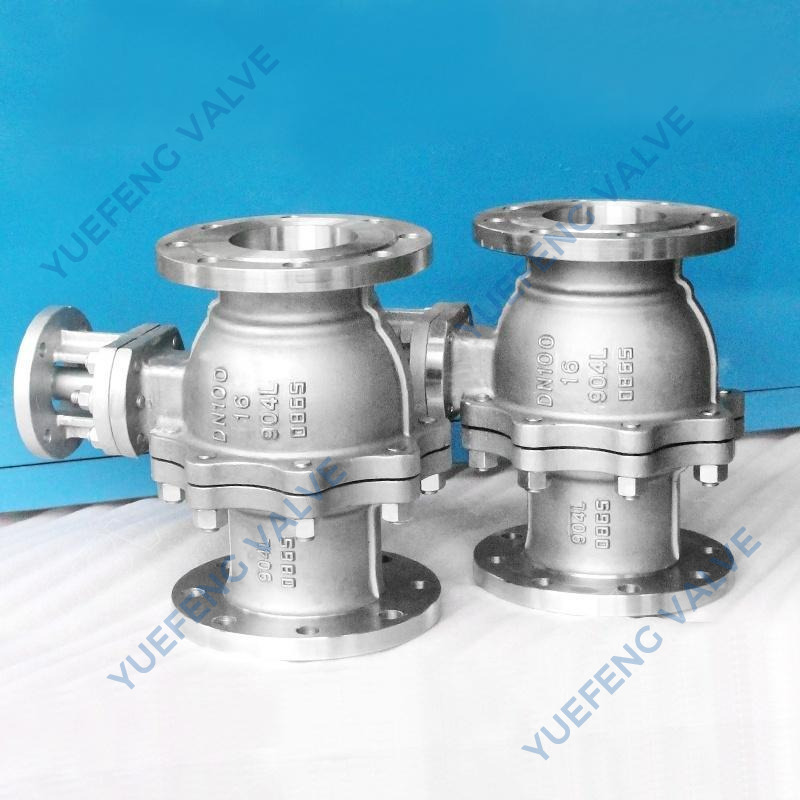
Different applications require drastically different internal mechanisms. You cannot use a universal approach for selection. Every design presents unique benefits and distinct engineering compromises.
A hinged disc swings open when fluid flows forward. Gravity and reverse flow pull the disc back against the seating surface. This simple mechanism creates a nearly unobstructed flow path. Engineers frequently specify them for high-flow applications. They perform exceptionally well in low-velocity environments.
However, you must consider a major trade-off. They generate a remarkably low pressure drop. Yet, they remain highly susceptible to water hammer. The disc must travel a long arc to close completely. Sudden flow reversals slam the heavy disc shut. This action creates massive pressure transients. Furthermore, you face strict installation limits. You can only install them in horizontal pipelines. They also work in upward-vertical lines. Never install them in downward-vertical pipes.
Forward flow lifts a heavy piston off its designated seat. The fluid pushes the internal globe mechanism upward. When flow stops, gravity forces the piston downward. This design resembles a standard globe valve body. Engineers use them heavily in high-pressure environments. They handle frequent flow reversals seamlessly.
The primary advantage lies in superior containment. You achieve an excellent, reliable seal. The piston design dampens closing forces naturally. However, this complex internal path creates a significant pressure drop. Fluid must turn 90 degrees twice to pass through. You must account for this substantial energy loss during system design.
A central spring assists the closing mechanism continuously. Spring tension forces the disc shut before reverse flow actually begins. This proactive closure prevents reverse velocity buildup. Engineers deploy them in systems requiring rapid closure. They effectively mitigate severe water hammer risks.
You face a slightly higher initial cracking pressure here. The forward flow must overcome the internal spring force. Despite this trade-off, they offer incredible versatility. They are universally orientable across your entire network. You can install them horizontally, vertically upward, or vertically downward.
A free-floating internal ball unseats during forward flow. Fluid pushes the ball into an adjacent chamber. When flow stops, the ball rolls back onto the seat. This mechanism provides a clear, smooth pathway. We highly recommend them for viscous fluids. They excel in raw wastewater applications.
They offer low-maintenance, self-cleaning operation. The ball rotates constantly, preventing uneven wear. However, they present certain engineering limitations. They are not ideal for high-pressure gas applications. They also struggle to provide high-precision sealing compared to piston designs.
Two separate spring-loaded plates fold inward under forward pressure. They resemble butterfly wings opening in the flow stream. When velocity drops, torsion springs snap the plates closed. Engineers specify them for space-constrained environments. They dominate large-diameter piping networks.
They feature a highly compact, lightweight footprint. You save considerable weight across large manifolds. However, the central hinge post obstructs the flow path. This obstruction presents a complex flow dynamic. It increases turbulence immediately downstream.
To simplify evaluation, review our technical comparison chart below.
Valve Mechanism | Best Application | Key Advantage | Primary Limitation |
|---|---|---|---|
Swing | Low velocity, high flow | Minimal pressure drop | High water hammer risk |
Lift / Piston | High-pressure gases/liquids | Excellent sealing | High pressure drop |
Spring-Loaded In-Line | Pump shut-off lines | Water hammer suppression | Requires higher cracking pressure |
Ball | Wastewater, slurries | Self-cleaning, non-clogging | Poor high-pressure gas sealing |
Dual Plate / Wafer | Tight spaces, large pipes | Lightweight and compact | Central post causes turbulence |
You must evaluate specific technical parameters before procurement. Ignoring these variables leads directly to system inefficiency.
Cracking pressure represents the exact minimum upstream pressure required. This pressure forces the internal mechanism to open. You must evaluate this metric against your standard line pressure. If cracking pressure remains too high, downstream flow suffers. A properly selected Check Valve opens fully during normal operation. You never want the disc hovering partially open. This partial opening restricts flow and damages internal springs.
The flow coefficient (Cv) defines volumetric efficiency. It represents how many gallons of water pass through per minute. It measures this flow at a standard one psi pressure drop. You must balance the need for high flow efficiency carefully. Every internal mechanism presents a physical obstruction. Higher Cv values indicate lower resistance. You must calculate acceptable pressure drops for your specific pumps.
Media characteristics dictate your physical material choices entirely.
Corrosives and Abrasives: Aggressive media destroys standard carbon steel quickly. You must specify appropriate alloys. We recommend Stainless Steel 316 or Duplex alloys for harsh chemical environments. Rubber liners also protect against abrasive slurries effectively.
Elastomers vs. Metal Seats: Soft seats utilize rubber or PTFE. They assess bubble-tight shutoff capabilities perfectly. However, they melt in extreme heat. Metal-to-metal seats handle high-temperature durability flawlessly. They provide rugged resistance but allow microscopic leakage rates.
Gravity constantly influences moving internal components. You must map valve limitations to your physical pipeline routing. Swing designs fail completely in downward vertical flows. Gravity keeps the disc open permanently. Spring-assisted mechanisms overcome gravity entirely. They allow horizontal, vertical upflow, and vertical downflow configurations. Always match the mechanical limits to your piping schematics.
Different industries face unique fluid handling challenges. Applying the correct mechanism solves these specific sector problems.
Water and Wastewater: Municipal systems handle heavy suspended solids daily. Facilities rely heavily on ball and swing models here. They provide unobstructed paths for thick sludge. They also prevent dangerous municipal backflow into drinking supplies.
Oil, Gas & Petrochemical: Refineries process volatile media under extreme pressure. Engineers focus on rugged piston and dual-plate designs. These units withstand punishing operational environments. They ensure strict API compliance while preventing explosive cross-contamination.
HVAC and Pump Systems: Commercial buildings manage massive chiller networks. These systems cycle massive pumps frequently. Facility managers focus on spring-loaded in-line mechanisms. They suppress devastating water hammer in critical boiler feed lines.
Pharmaceutical and Food & Beverage: Cleanliness overrides all other engineering concerns here. Plants require highly specialized sanitary equipment. They focus on crevice-free internal bodies. These units support CIP (Clean-in-Place) and SIP (Steam-in-Place) protocols. Materials must remain strictly FDA and 3A compliant.
Theoretical selection often fails during practical implementation. You must navigate several real-world operational hazards successfully.
Many technicians simply match the valve size to the pipe size. We call this the oversizing trap. You must size equipment for actual flow rate instead. Low fluid velocity cannot hold an oversized disc fully open. The disc hovers near the seat momentarily. As velocity drops further, it closes. Pressure builds instantly and pushes it open again. The disc rapidly bounces against the seat continuously. We refer to this destructive phenomenon as "chatter." It destroys hinges and shatters internal springs rapidly.
Closing speed defines water hammer mitigation success. You must address the implementation reality of pump shut-off scenarios. When a pump trips, fluid reverses direction instantly. Slow-closing mechanisms allow reverse velocity to build momentum. When the disc finally slams shut, it generates a massive shockwave. Fast-closing, spring-assisted mechanisms are mandatory here. They snap shut precisely before reverse flow initiates. This proactive closure prevents the shockwave entirely.
You must evaluate maintenance accessibility during the design phase. Internal components wear out eventually. Choosing inline-repairable designs saves massive amounts of labor. Many swing designs feature bolted top covers. You can remove the cover and replace the hinge directly. This eliminates complete line removal entirely. Avoid welded-in designs requiring pipeline cutting for simple seal replacements. Prioritize designs offering easy internal access to minimize facility downtime.
You need a systematic approach to finalize your engineering specifications. Follow these specific steps to guarantee optimal system performance.
Step 1: Define Flow Parameters: Do not guess your system metrics. Map your exact minimum and maximum flow rates precisely. Record normal media temperatures and ultimate pressure boundaries. These data points form your absolute baseline.
Step 2: Filter by Orientation and Space: Review your physical piping schematic carefully. Eliminate completely incompatible types immediately. If you have tight horizontal spaces, filter out bulky swing models. Specify wafer models for severely space-constrained environments.
Step 3: Evaluate Operational Efficiency: Weigh your upfront component choices against expected maintenance intervals. Analyze energy losses stemming from restricted flow paths. High pressure drops force pumps to consume more electricity. Prioritize components offering longer lifespans and smoother internal flow dynamics.
Step 4: Consult with Manufacturers: Never finalize a specification blindly. Request comprehensive flow curves from your vendors. Demand precise pressure drop charts. Validate all your theoretical assumptions against manufacturer data before signing purchase orders.
Check valve selection remains a critical system-protection exercise. You cannot treat these components as mere pipeline accessories. Incorrect specification risks your pumps, your personnel, and your entire operation. We advise buyers to prioritize actual flow data relentlessly. Always prioritize closing speed over simple pipe diameter matching. This strict engineering discipline ensures long-term operational reliability.
You now possess a clear evaluation framework. Stop accepting generic equipment for highly specific fluid challenges. Assess your media, evaluate your orientation, and calculate your required Cv. Contact your engineering support team today to review your current network. Download a detailed specification worksheet from a trusted vendor. Request a technical consultation to secure the exact protection your facility requires.
A: A check valve is a single mechanical component designed to prevent reverse flow in standard piping. A backflow preventer is a complex, testable safety assembly. Municipalities require backflow preventers to protect public drinking water from contamination. They typically contain multiple independent check mechanisms and specialized relief valves.
A: You must determine size based on flow rate and fluid velocity, not just line size. Calculate your required Flow Coefficient (Cv). Ensure normal system flow provides enough velocity to hold the internal mechanism fully open. Sizing solely by pipe diameter often causes premature mechanical failure.
A: It depends entirely on the specific mechanical design and flow direction. Spring-loaded mechanisms work flawlessly in both upward and downward vertical lines. However, standard swing designs only function in upward-flowing vertical pipes. Gravity forces swing discs open permanently if installed in downward-flowing vertical pipes.
A: Chatter occurs when flow velocity remains too low to keep the internal mechanism fully open. The disc rapidly bounces against the seat, causing severe damage. You fix this by properly sizing the equipment based on actual flow rates. Alternatively, you can adjust internal spring tension settings.


