

close
Choose Your Site
Global
Social Media
Views: 0 Author: Site Editor Publish Time: 2026-08-04 Origin: Site


Industrial piping systems rely heavily on proper flow control mechanisms. A simple backflow event can instantly compromise an entire processing facility. This makes the Check Valve one of the most critical safeguards in your pipeline. Reverse flow causes catastrophic system failures like severe water hammer. It damages expensive downstream equipment, including main pumps and centrifugal compressors. Choosing the wrong valve type also drives up daily energy consumption. Massive pressure drops force system pumps to work much harder. This frequently triggers catastrophic failures and unplanned facility downtime.
This guide closely evaluates the mechanical differences between spring and swing mechanisms. We explore key operational trade-offs to aid your exact specification process. You will learn how sizing considerations directly dictate your best hardware choice. Fluid dynamics ultimately determine the safest unit for your specific application. Proper engineering selection guarantees long-term system stability and daily operational safety.
Swing check valves rely on flow velocity and gravity, offering minimal flow restriction but requiring specific installation orientations and posing a higher risk for water hammer.
Spring check valves utilize mechanical assistance to close before flow reverses, effectively mitigating water hammer and allowing omnidirectional installation, though at the cost of a higher pressure drop.
Media compatibility dictates selection: Swing designs are standard for slurries and wastewater (debris-tolerant), while spring designs are preferred for clean fluids and HVAC systems.
Establishing a proper operational baseline requires understanding fundamental fluid dynamics. A Check Valve performs one essential job in any pipeline architecture. It allows fluid to flow safely in a single, predetermined direction. Once forward momentum stops, the internal mechanism must shut very quickly. This action strictly prevents any reverse flow from traveling backward through the entire line.
Engineers always face a primary decision-stage compromise during system design. They must carefully balance minimal head loss against rapid closure speed. Low head loss drastically improves overall system efficiency. It reduces the daily workload on your expensive centrifugal pumps. However, faster closure offers significantly better infrastructure protection. You rarely get both operational benefits equally in one single hardware design.
Hydraulic shock, commonly called water hammer, poses a massive infrastructure threat. It happens when reversing fluid suddenly hits a fully closed valve. The resulting kinetic shockwave can completely rupture heavy industrial pipes. It easily destroys expensive pipe supports and damages sensitive adjacent instrumentation. Backflow can also spin centrifugal pumps backward forcefully. This unintended rotation rapidly destroys internal impellers and mechanical seals.
Valve closure timing relative to flow reversal remains absolutely crucial. It serves as the primary metric for evaluating safety in high-pressure systems. If a mechanism closes too slowly, the reversing fluid builds immense backward momentum. The sudden halt of this intense momentum creates incredibly dangerous pressure spikes. We must prioritize appropriate closure speeds manually. This proactively mitigates these severe operational risks perfectly.
Swing mechanisms feature a very simple, time-tested structural design. They use a heavy hinged disc suspended directly inside the main valve body. Fluid pressure pushes this disc open smoothly during normal forward flow. When forward velocity drops, gravity naturally pulls the heavy disc downward. Backflow then presses it firmly against the internal seat to create a tight seal. This closing action relies entirely on external physical forces rather than internal mechanical tension.
Common Variations
Manufacturers produce several specific swing styles for different industrial environments:
Standard Swing: These feature basic flanged or threaded bodies. Engineers specify them heavily for general utility in straightforward industrial environments. They offer highly reliable performance under predictable, steady flow conditions.
Lever and Weight/Spring: These externally modifiable designs let operators adjust closing speeds manually. Technicians can move heavy weights along an external lever arm. This action fine-tunes the physical reaction time. It helps limit the severe impacts of destructive valve slam.
Resilient Seated: These specialized models utilize robust rubber-coated discs. Manufacturers also use durable elastomer seats. They provide exceptional bubble-tight sealing capabilities. You will find them highly effective in lower-pressure systems. Metal-to-metal seals often leak under these specific low-pressure conditions.
Primary Applications
We frequently see these valves dominating wastewater management facilities. Municipal water distribution networks also rely heavily on them daily. They excel primarily in systems prioritizing completely unobstructed flow. Solid debris and thick sludge pass through the open disc path very easily. They do not trap heavy particulates or stringy materials.
Operational Limitations
You face strict physical installation limits here. Crews must install them horizontally in most standard piping setups. Vertical installation remains conditionally acceptable only if the fluid travels strictly upward. Gravity must always be able to pull the disc closed securely. These valves remain highly susceptible to severe hydraulic shock. If flow reverses rapidly before gravity closes the disc, a massive slam occurs. This damages the surrounding piping severely.
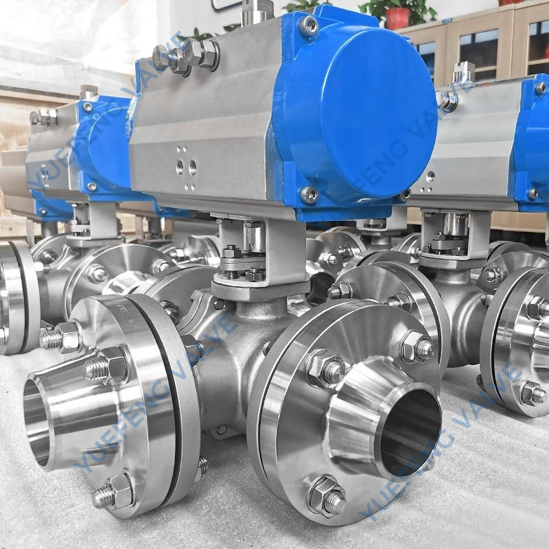
Spring-loaded designs operate using highly proactive mechanical force. They feature a strong internal spring pushing directly against a disc or plate. Fluid pressure must physically overcome this specific spring tension to open the pathway. As forward velocity eventually drops, the spring forces the mechanism closed immediately. This crucial action happens entirely before any backflow actually begins.
Common Variations
Engineers often specify these three main mechanical configurations:
In-line / Axial Flow: This highly compact, concentric design suits high-pressure clean piping perfectly. It forces fluid to travel around an aerodynamic central component. This minimizes turbulence while ensuring rapid, reliable closure.
Dual-Plate (Wafer): This excellent space-saving design splits the main disc into two spring-loaded halves. It fits very easily between standard pipe flanges. This dramatically reduces the overall pipeline installation footprint.
Silent Check Valves: Manufacturers engineer these specialized units specifically with internal damping features. The internal geometry aggressively eliminates destructive valve slam. They act incredibly fast to stop reversing water columns instantly.
Primary Applications
These advanced mechanisms dominate pump discharge lines across numerous industrial sectors. Commercial HVAC systems rely on them heavily for reliable fluid control. You will also find them securing boiler feeds and high-rise vertical piping layouts. They protect critical infrastructure perfectly from severe dynamic shocks.
Operational Limitations
The internal components naturally create increased flow resistance. You will clearly observe a higher cracking pressure required to open them. The system also suffers continuous head loss during daily operation. Furthermore, the internal spring and central guide act exactly like a physical strainer. They can easily trap passing debris or suspended solids. This physical characteristic makes them highly unsuitable for handling raw sewage. They will fail quickly in heavy slurry applications.
Comparing these mechanisms directly clarifies the complex specification process. Let us examine the four primary dimensions you must evaluate carefully before final procurement.
Swing designs require an adequate, perfectly horizontal pipe run. Vertical installation is conditionally acceptable only if the flow points strictly upward. They also feature very bulky external face-to-face dimensions. In contrast, a spring Check Valve works omnidirectionally. You can install it vertically, horizontally, or even at an awkward angle safely. Wafer and in-line types offer significantly smaller face-to-face dimensions. They easily solve incredibly tight spatial constraints in crowded mechanical rooms.
A standard swing mechanism features a fully open, full-port design. This structural layout results in minimal fluid turbulence. It provides a exceptionally high flow capacity (Cv). It guarantees exceptionally low ongoing energy consumption for system pumps. Meanwhile, a spring-loaded disc remains directly in the active flow path. The system requires continuous pump pressure to keep the internal spring compressed. This physical reality results in continuous head loss. It causes slightly lower overall pumping efficiency over time.
Swing variants rely entirely on reactive closure. Gravity takes precious time to pull the heavy disc down securely. This mechanical delay creates a critically high risk of violent valve slam. Spring variants execute highly proactive closure instead. The internal spring shuts the disc instantly as soon as forward velocity drops. Engineers officially class them as "non-slam" or "silent" control mechanisms. They aggressively protect sensitive piping infrastructure from destructive shockwaves.
The swing design offers an almost totally unobstructed internal pathway. It allows heavy solids, thick sludge, and stringy materials to pass very easily. Spring designs pose a completely different operational challenge. Their internal moving components essentially act as physical strainers. They create severe clogging risks rapidly when handling dirty media. You must avoid them strictly when processing untreated municipal wastewater.
Evaluation Dimension | Swing Mechanism | Spring Mechanism |
|---|---|---|
Closure Action | Reactive (Gravity/Flow) | Proactive (Mechanical) |
Water Hammer Risk | High Risk (Slam prone) | Low Risk (Non-slam) |
Pressure Drop | Low (Full port flow) | Moderate to High |
Media Suitability | Slurries, Raw Wastewater | Clean Water, Gas, Steam |
Install Orientation | Horizontal preferred | Omnidirectional |
Maintenance procedures differ wildly between the two distinct mechanical designs. Swing valves often feature a highly convenient top-entry bonnet. This bolted cover allows for very quick internal visual inspection. Maintenance crews can perform complete disc replacement efficiently. They do this without removing the massive valve body from the active pipeline. Conversely, spring in-line valves typically require full physical removal from the piping. This harsh reality makes routine maintenance much more labor-intensive and time-consuming.
Wear and Tear Risks (Chattering)
You must carefully address the major operational risk of oversized valves. Many junior designers mistakenly match the valve size directly to the pipe size. If actual flow remains insufficient to keep the valve fully open, severe problems occur. Both hardware types will rapidly bounce open and closed. Engineers officially call this highly destructive phenomenon "chattering." It leads directly to premature internal seat degradation. It also causes rapid hinge pin or internal spring failure. You must size the valve based on actual flow rates, not just pipe diameter.
Material Selection and Compliance
System longevity requires specifying highly accurate body and trim materials. Highly corrosive media demands internal components made from robust 316SS. Specialized bronze also works exceptionally well for specific marine environments. Standard municipal wastewater applications often utilize durable ductile iron bodies. Always ensure your exact material selections comply with major industry standards. Organizations like API and AWWA dictate strict metallurgical requirements for public safety. You must follow these exact testing guidelines rigorously.
Selecting the perfect Check Valve requires a highly structured, logical approach. Follow this exact technical framework to finalize your engineering specification perfectly:
Step 1: Analyze the Fluid. Evaluate the specific media passing through the line carefully. If it contains raw wastewater, thick sludge, or heavy debris, bias your choice immediately toward a swing design. If the system moves exclusively clean water, natural gas, or pure steam, proceed to the next step.
Step 2: Assess Installation Geometry. Look at your physical piping layout very carefully. If you have a vertical pipe featuring downward flow, you face strict operational limits. Tight face-to-face spatial limits also restrict your viable options heavily. Both unique scenarios strictly mandate a compact spring or dual-plate configuration.
Step 3: Evaluate Pumping Dynamics. Study your mechanical pump operational profiles extensively. High-head pumps often feature very rapid, aggressive shut-off profiles. This dynamic action creates a incredibly severe water hammer risk. These intense dynamic conditions strictly mandate a proactive spring or silent design.
Step 4: Balance Efficiency Versus System Risk. Review your long-term operational engineering priorities carefully. You must weigh the continuous daily energy demands caused by a spring mechanism's pressure drop. Compare this metric directly against the catastrophic infrastructure risk of a standard swing mechanism's potential slam. Choose the option minimizing your greatest operational threat.
Engineering system design always requires careful, calculated compromise. Neither valve type remains objectively superior across all operational scenarios. Your long-term success depends entirely on matching the mechanical action perfectly to your specific system. You must account for fluid properties, spatial layout constraints, and internal pressure dynamics. A well-matched control mechanism ensures decades of highly reliable daily performance. A poor match guarantees frequent breakdowns and dangerous safety hazards.
We strongly encourage buyers to verify all operational parameters meticulously. Always consult exact flow coefficients (Cv) closely before making a final decision. Calculate your specific system cracking pressures highly accurately. Review detailed manufacturer engineering submittals thoroughly before finalizing any major procurement. Taking these proactive engineering steps protects your critical piping infrastructure from entirely preventable catastrophic failures.
A: Yes, but only under highly specific conditions. You can install it in vertical lines where fluid flows strictly upward. Gravity must be able to pull the internal disc down securely. This ensures the mechanism closes properly when forward flow stops. Downward vertical flow completely prevents the mechanism from sealing correctly. Never install swing designs in downward-flowing vertical pipes.
A: Cracking pressure represents a critical operational threshold. It defines the minimum upstream fluid pressure required to overcome internal mechanical resistance. This resistance typically comes from internal friction, gravity, or spring tension. Once the fluid reaches this exact pressure level, it forces the disc open to initiate forward flow. Engineers must calculate this value accurately for system efficiency.
A: This disruptive noise usually indicates severe valve slam. It occurs due to delayed closure, which happens frequently in standard swing valves. Reversing fluid forcefully slams the heavy disc shut against the seat. Alternatively, it can indicate "chattering." Chattering occurs when an oversized valve cannot fully open under current low-flow conditions, causing the internal disc to rapidly bounce.
A: The ideal choice depends entirely on the fluid type. For clean water sump applications, engineers prefer spring or silent check valves. These proactive designs effectively prevent the loud "thud" of dropping water columns. For sewage ejectors or wastewater sumps, you must use specialized swing or ball configurations. These specific designs safely pass solid waste and debris without clogging.


