

close
Choose Your Site
Global
Social Media
Views: 0 Author: Site Editor Publish Time: 2026-10-27 Origin: Site


Can a standard pipe suddenly become a hidden bomb? It sounds alarming. Yet, trapped fluid causes severe safety hazards in industrial environments every single day. When block valves close, they isolate liquid within their internal voids. Subject this fixed volume to even minor temperature changes, and the fluid expands. The result is a massive internal pressure spike.
In this guide, we dive deep into the physics behind thermal expansion. We will also break down effective relief solutions from an engineer's perspective. By understanding the mechanics of internal pressure, you protect your infrastructure, ensure regulatory compliance, and maintain a safe operating environment.
Key Takeaways
Trapped Pressure is a Silent Threat: Liquid trapped in a closed valve cavity experiences severe pressure spikes due to thermal expansion. This easily causes seat failure or body rupture.
Automatic Relief is Essential: Modern systems rely on engineered relief paths. Single Piston Effect seats automatically vent excess pressure without human intervention.
Design Matters: Heavy-duty trunnion architectures are specifically designed to handle severe pressure differentials and feature built-in automatic venting.
Application Dictates the Solution: Your choice depends entirely on the media, operating temperature, and industry codes like API 6D. Solutions range from upstream relief holes to high-pressure fully welded bodies.
To fully grasp the mechanics of pressure relief, we must first look inside the hardware. How does fluid interact with internal components during operation? Picture an operator closing a 12-inch isolation valve on a crude oil line. The external action is simple. The internal fluid dynamics, however, are highly complex.
A quarter-turn rotational device uses a perforated, sphere-shaped disk to stop or start flow. This fundamental design is highly efficient. It provides a tight seal and a remarkably low pressure drop. Critical internal components include the hollow pivoting sphere, the soft or metal seat rings that create the seal, the outer pressure-retaining body, and the stem connecting the actuator.
The body cavity is the empty interstitial space between the exterior surface of the sphere and the interior wall of the housing. When the unit is fully open, the bore aligns with the pipeline. Fluid flows freely. During this state, fluid also naturally fills the surrounding interstitial space.
Rotate the stem 90 degrees to the closed position. The seats now press tightly against the solid sides of the sphere. This action isolates the fluid inside the bore and the fluid in the surrounding space. The liquid is completely sealed off from upstream and downstream pipeline pressures. Under normal static temperatures, this trapped volume is harmless. Let external environmental variables change, and this fixed volume becomes a massive engineering challenge.
Thermal expansion is the primary catalyst for internal failure. Temperatures in industrial piping systems are rarely static. Understanding the physical behavior of trapped liquids is non-negotiable for safe system design.
We all know liquids are virtually incompressible. They possess a massive bulk modulus. It takes a tremendous amount of force to reduce their volume even slightly. Conversely, heating a liquid increases its molecular kinetic energy. Its volume desperately wants to expand.
Imagine a pipeline exposed to the blistering afternoon sun. Liquid trapped inside a rigid, closed cavity cannot physically expand. The fluid cannot increase its volume to accommodate the added thermal energy. Instead, that energy violently converts into internal pressure. In closed systems containing water or hydrocarbons, a temperature rise of just 1 degree Celsius can cause the internal pressure to spike by hundreds of PSI.
Failing to implement proper ball valve pressure management strategies leads to severe mechanical failures. It causes crippling system downtime and hazardous safety incidents. Field engineers typically observe three primary failure modes:
Seat Blowout and Deformation: Soft seating materials like PTFE or PEEK have strict structural limits. Skyrocketing internal force pushes the seats outward. This permanently deforms the rings or blows them entirely out of their grooves. Once compromised, the seal leaks continuously.
Equipment Locking: Excessive internal pressure pushes outward against the sphere and seats with immense force. This drastically increases friction. When an automated actuator attempts to open the line, the required torque easily exceeds the motor's capacity. The system effectively locks up.
Catastrophic Shell Rupture: Extreme thermal expansion in lower-grade cast bodies can exceed the metal's tensile strength. This results in a catastrophic rupture. Toxic or flammable media instantly releases into the environment.
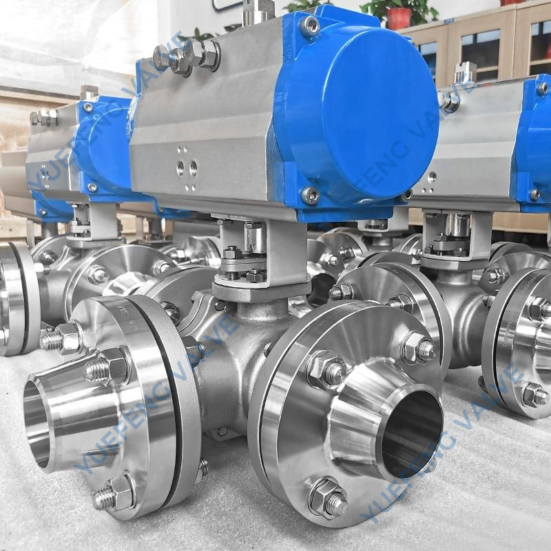
To mitigate these thermal dangers, engineers developed several mechanical solutions to ensure reliable ball valve cavity pressure relief. The ultimate goal is simple. Provide a safe, automated path for excess force to vent before it damages the structural integrity of the housing.
The most efficient solution is integrating self-relieving seats. Instead of relying on external modifications, the internal seat rings act as miniature safety valves. When the internal force exceeds a specific threshold above the pipeline pressure, the seat automatically yields. A small amount of fluid escapes back into the pipeline. The pressure spike is instantly neutralized.
Understanding seat architecture is crucial for specifying the correct hardware. The two primary designs in high-performance applications are Single Piston Effect and Double Piston Effect. Let us look at how they compare in the field.
Feature | Single Piston Effect (SPE) | Double Piston Effect (DPE) |
|---|---|---|
Sealing Direction | Unidirectional per seat | Bidirectional per seat |
Cavity Relief | Automatic (Self-relieving) | Traps pressure inside |
External PRV Required? | No | Yes, absolutely necessary |
Primary Use Case | Standard pipeline isolation | Double Isolation and Bleed (DIB) |
An SPE design pushes the seat away from the sphere when internal forces rise, venting into the line. A DPE design pushes the seat against the sphere regardless of where the force originates. Because DPE seats trap fluid, they demand an external venting mechanism.
For simpler architectures where spring-loaded seats are mechanically unfeasible, we utilize a vented sphere. We drill a small hole through the upstream side. This connects the internal bore directly to the external surface.
When closed, this vent hole ensures the internal space remains continuously equalized with the upstream pipeline. The fluid is never truly isolated. Pressure cannot build up. This method is highly effective and serves as a mandatory standard in cryogenic applications. Just remember, it renders the flow strictly unidirectional.
Systems requiring DPE seats for ultimate bidirectional sealing integrity will not self-relieve. To manage overpressure here, an external Pressure Relief Valve must be threaded or piped directly into the housing. If a spike occurs, the external unit opens and vents the fluid safely to a designated drain or flare system.
The structural framework dictates how effectively the equipment handles internal fluid dynamics. Industrial piping relies on two main categories: floating and trunnion mounted.
In a floating design, the sphere is suspended between the two seats. Line pressure physically pushes the entire sphere downstream when closed. It forces it tightly into the downstream seat to create the seal.
Because the sphere must shift laterally, implementing reliable spring-loaded SPE seats is difficult. Floating designs are inherently more susceptible to trapped fluid issues. To achieve safe venting in a floating architecture, engineers almost exclusively rely on the upstream vented hole modification.
A trunnion mounted ball valve is engineered specifically for severe service. The sphere is anchored by a top stem and a bottom shaft. It rotates freely but cannot move laterally downstream.
Because the sphere is fixed, the seats are dynamic. Spring-loaded seat rings float against the fixed surface. This architecture is perfectly suited for SPE seats. The springs maintain the initial seal. The seats easily move backward to vent excess force without affecting the position of the sphere. Trunnion configurations provide highly reliable, automatic venting. They remain the gold standard for heavy industrial pipelines.
Designing a resilient piping system requires strict adherence to international engineering codes. Regulatory bodies establish rigorous testing criteria to ensure safety mechanisms function reliably under extreme conditions.
The American Petroleum Institute standard 6D is the definitive specification for pipeline equipment. API 6D explicitly states that any block unit capable of trapping liquid must be provided with a relief mechanism if subjected to temperature fluctuations. ASME B16.34 governs the pressure-temperature ratings of the metal housing. Proper venting is essential to prevent exceeding these structural yield limits.
Looking at recent industry developments, there is a distinct shift in how facilities approach overpressure scenarios. Global surges in LNG processing, deep-water offshore drilling, and hydrogen transport are pushing systems to unprecedented extremes. Cryogenic liquids expand exponentially as they phase-change from liquid to gas upon absorbing ambient heat.
Consequently, operators are rapidly moving away from traditional bolted designs in critical zones. We are seeing a massive adoption of fully welded configurations integrated with advanced SPE/DPE seating combinations. This dual approach complies with increasingly stringent fugitive emission regulations. It guarantees fail-safe internal venting without relying on external PRVs, which frequently foul in harsh environments.
Selecting the correct hardware requires a methodical evaluation of your specific process conditions. A generic approach always leads to costly premature failures.
Procurement managers and piping engineers must collaborate. Evaluate the exact nature of the fluid. Is it a compressible gas or an incompressible liquid? Will the pipeline face solar radiation, steam tracing, or adjacent heat exchangers? If incompressible liquids exist in fluctuating temperature zones, automatic venting is mandatory. Calculate the maximum potential pressure delta to ensure the selected seat materials yield at the correct threshold without permanent extrusion.
For extreme containment, particularly in buried pipelines or subsea applications, bolted body joints become potential leak paths under severe tensile stress. Fully welded bodies offer superior structural integrity. By eliminating flanges and bolts, the shell becomes a single robust containment vessel.
For critical infrastructure requiring maximum containment alongside reliable automatic venting, an engineered solution like the Bare Stem High-Pressure Fully Welded Ball Valve is highly recommended. These units utilize forged steel bodies, zero leak path designs, and trunnion mounted architectures with SPE seats. Even under extreme thermal expansion, internal forces are safely managed without compromising external shell integrity.
The reliability of a relief mechanism depends entirely on manufacturing precision. Seat springs must be calibrated perfectly. Dimensional tolerances between the sphere and the SPE seats must be exact.
Work with manufacturers who maintain rigorous API testing protocols. Evaluate a comprehensive range of equipment tailored for specific containment requirements. Partnering with experienced engineering teams guarantees your infrastructure is protected from the silent threat of trapped fluid.
Proper pressure management is not an optional upgrade. It is a vital safety requirement for modern piping systems. Managing thermal expansion prevents dangerous structural failures, costly downtime, and environmental hazards. Whether your facility requires a simple upstream vented design or a heavy-duty fully welded configuration with self-relieving seats, engineered solutions protect your workforce. Evaluate your current systems today. Choose reliable, API-compliant equipment from trusted manufacturers to ensure complete operational longevity.
Automatic body cavity relief is a built-in safety mechanism utilizing Single Piston Effect seats. It allows excess fluid pressure trapped inside the closed housing to automatically push the seat slightly away from the sphere. This vents the overpressure safely back into the adjacent pipeline once a specific threshold is reached.
Liquids are virtually incompressible. When liquid is trapped inside a closed space and subjected to heat, it attempts to expand. Because the volume is fixed, this thermal expansion causes internal force to rise exponentially. This permanently deforms soft polymer seats, locks the equipment in place, or causes the metal housing to rupture.
Yes, but it generally requires a mechanical modification. Because floating designs rely on line pressure to push the sphere into the downstream seat, they easily trap fluid. To safely relieve this, manufacturers drill a small relief hole into the upstream side of the sphere to ensure continuous equalization with the upstream line.
SPE seats are self-relieving. They utilize line pressure to maintain a seal but allow internal force to push the seat open and vent. DPE seats are designed to seal from both directions regardless of the pressure source. This means they trap fluid and require an external pressure relief valve to prevent structural damage.
A cavity-filled unit is equipped with specially molded polymer seat inserts like PTFE that physically occupy the empty voids inside the housing. By eliminating the dead space where fluid normally accumulates, it prevents media from getting trapped. This is crucial for sanitary food applications or handling fluids that crystallize when stagnant.
Manufacturers follow strict API 6D testing procedures. The unit is partially opened, filled with water, and then fully closed to isolate the cavity. Pressure is artificially introduced into the center space through a test port. Engineers monitor the gauges to ensure the seats automatically yield and vent the pressure into the bore before reaching dangerous structural limits.
The exact venting threshold depends on the manufacturer's spring calibration and industry standards. However, under API 6D guidelines, the cavity pressure relief must trigger at a pressure no greater than 1.33 times the valve's pressure rating for that specific temperature. This ensures the pressure drops well before it threatens the integrity of the metal shell.


