

close
Choose Your Site
Global
Social Media
Views: 0 Author: Site Editor Publish Time: 2026-10-21 Origin: Site


Extreme industrial pressure destroys standard plumbing components fast. Sometimes, complete failure occurs in a matter of hours. Volatile fluids forced through pipelines at high velocities trigger severe cavitation. They generate deafening aerodynamic noise. They cause violent mechanical vibrations. Ultimately, these destructive forces tear apart internal trims, leading to catastrophic system failure and costly plant downtime.
How do modern processing facilities solve this? By stepping away from basic, unbalanced designs. In this guide, we explore how a cage-sleeve architecture systematically overcomes these exact physical limitations. Leveraging a balanced plug design and heavy-duty internal guiding absorbs kinetic energy. It ensures unwavering process stability even under extreme pressure drops.
Unmatched Stability: Cage-sleeve architectures utilize a balanced plug design. This significantly reduces the actuator force required to operate smoothly under extreme pressure differentials.
Cavitation and Noise Control: Engineered cage window designs act as a mechanical buffer. They mitigate the damaging effects of cavitation and dampen aerodynamic noise to meet strict occupational safety standards.
Superior to Single-Seat in High-Pressure: Single-seat valves are effective for low-leakage, small-scale needs. However, cage-sleeve designs dominate in high-pressure drop and high-flow industrial scenarios.
Streamlined Maintenance: The top-entry structural design allows technicians to perform quick internal parts replacement. There is no need to remove the heavy valve body from the primary piping.
Versatile Industrial Applications: These components are absolutely essential for power generation, petrochemical refining, and oil and gas extraction where steady flow is non-negotiable.
To understand why certain fluid management systems operate flawlessly under extreme stress while others fail prematurely, engineers must examine the internal mechanics regulating the flow. The cage-sleeve design represents a significant structural advancement over basic globe valves. It is built specifically to manage violent fluid dynamics.
At its foundation, this valve consists of a plug that moves vertically inside a precisely machined cylindrical cage. Industry professionals commonly refer to this as the sleeve. Unlike simpler designs where the plug relies solely on a slender stem or a bottom seat ring for alignment, the cage acts as a continuous, massive guide for the plug. Imagine a heavy piston sliding perfectly within an engine cylinder. This massive guiding surface area prevents lateral oscillation, even when the plug is buffeted by turbulent, high-velocity flows.
This cylindrical cage is perforated with specially shaped windows. As the pneumatic or electric actuator lifts or lowers the plug, it uncovers or covers these openings. The geometry of these windows dictates the exact flow rate passing through the pipeline. Therefore, the cage serves a dual purpose. It acts as the primary flow-characterizing element and provides robust mechanical support to eliminate plug vibration. Specifying a high-pressure control valve with this specific trim fundamentally alters how kinetic energy is managed within the pipe.
The defining feature of this architecture is its ability to maintain steady flow through a balanced plug concept. In standard unbalanced valves, high-pressure fluid pushes directly against the bottom or top of the plug. This creates an immense hydraulic force. Overcoming that force requires a massive, energy-intensive actuator.
In a cage-sleeve design, balancing holes drilled vertically through the plug allow the fluid pressure to equalize in the chamber directly above it. Because the pressure is distributed evenly on both the top and bottom surfaces, the net hydraulic force acting on the plug drops to nearly zero. This elegant equalization prevents the high-pressure fluid from slamming the valve shut or blowing it open.
Global processing facilities are currently pushing operational limits further than ever before. Supercritical thermal power plants now operate at steam pressures exceeding 3,200 psi. Deep-water offshore extraction brings aggressive, high-pressure multiphase fluids to the surface at terrifying velocities. Simultaneously, environmental agencies are enforcing strict fugitive emission and occupational noise limits.
Plants can no longer rely on legacy single-seat valves to handle these parameters. Migrating to multi-stage, cage-guided architectures is no longer just a premium upgrade. It is a mandatory baseline for modern engineering compliance. Managing these dynamic forces requires heavy-duty equipment engineered to absorb and dissipate destructive kinetic energy before it compromises pipeline integrity.
Two of the most destructive phenomena in fluid mechanics are cavitation and flashing. Cavitation occurs when fluid velocity increases as it passes through the narrowest part of the valve, known as the vena contracta. The local static pressure drops below the liquid vapor pressure. Vapor bubbles instantly form. As the fluid exits the restriction and pressure recovers, these bubbles collapse violently.
The resulting micro-jets blast into metal surfaces. They generate shockwaves that can pit and erode hardened steel within hours, leaving internal trims looking like Swiss cheese. Flashing is a related issue where the downstream pressure never recovers above the vapor pressure. The liquid permanently transitions into a high-velocity, abrasive vapor-liquid mixture.
A cage-guided valve combats these issues through staged pressure reduction. Instead of forcing the fluid through one massive pressure drop, specialized cages break the pressure reduction into multiple smaller, manageable stages. Utilizing multi-hole or labyrinth geometries, this controlled diffusion prevents the fluid pressure from ever dipping below the vapor pressure. It stops the root cause of cavitation before it starts.
Industrial plant noise is heavily regulated. High-velocity gas expansion and liquid cavitation generate severe aerodynamic and hydrodynamic noise. In poorly designed systems, this often exceeds 110 decibels. This acoustic energy translates directly into mechanical vibration. It causes pipe fatigue, loosened fittings, and eventual catastrophic failure.
The cage sleeve effectively acts as an acoustic diffuser. By forcing the fluid stream to divide into dozens or hundreds of smaller micro-jets through the cage windows, the fluid kinetic energy dissipates through controlled turbulence and friction. This mechanism shifts the noise frequency to higher spectrums that are more easily absorbed by the pipe wall. It significantly lowers overall decibel levels and prevents pipe-rattling vibrations.
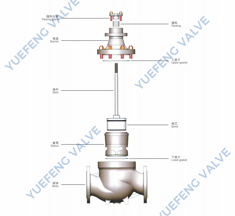
Engineers frequently debate single-seat versus cage-sleeve designs during the specification phase. While both serve to regulate flow, their structural differences dictate their survival rate in severe service environments.
A single-seat valve utilizes a relatively simple design consisting of a single valve plug and a single seat ring. Because there is only one sealing surface, it is highly effective at achieving tight shut-off with low leakage rates. However, the plug is typically top-guided by the stem alone. This leaves it vulnerable to lateral forces and turbulence.
In contrast, a cage-sleeve valve features a plug guided along its entire stroke by the surrounding heavy-duty cage. This massive guiding surface area provides exceptional lateral stability. The most critical distinction lies in how each valve handles high pressure. Single-seat valves are inherently unbalanced. The full force of the upstream fluid pressure acts directly against the surface area of the plug. The actuator must exert an immense amount of thrust simply to keep the valve closed.
Cage-sleeve valves thrive in these exact conditions. Because the fluid pressure is equalized through the plug balancing holes, the unbalanced forces are virtually eliminated. This allows the valve to operate smoothly under extreme pressure drops using a significantly smaller, more responsive actuator.
Feature | Single-Seat Control Valve | Cage-Sleeve Control Valve |
|---|---|---|
Plug Balance | Unbalanced High force required | Balanced Low force required |
Guiding Mechanism | Top/Stem Guided | Cage Guided High stability |
High-Pressure Drop Suitability | Poor to Moderate | Excellent |
Cavitation Resistance | Low | High with specialized cages |
Maintenance Speed | Slow Threaded seats may seize | Fast Drop-in internals |
The empirical advantages of the cage-guided design make it the standard choice for the most demanding industrial sectors. Wherever fluid energy is high and process stability is non-negotiable, these valves are deployed.
In the oil and gas sector, wellhead control and gas injection involve extreme pressures that fluctuate wildly. Extracted fluids often contain entrained sand or debris. Cage-sleeve valves are utilized here because their robust guiding mechanism resists the violent buffeting of high-velocity multiphase flows. For abrasive conditions, manufacturers utilize hardened cage materials, such as solid tungsten carbide or Stellite overlays. This resists erosion while maintaining precise flow control over the lifespan of the well.
Modern power generation relies on steam systems operating at extreme temperatures. Boiler feedwater control and steam bypass systems are critical nodes. Handling high-temperature steam requires a valve that offers exceptional thermal stability. The symmetrical design of the cage sleeve ensures uniform thermal expansion. It prevents the plug from binding or galling inside the valve body during rapid temperature transients.
Chemical refining processes, such as fluid catalytic cracking, require absolute flow stability to maintain reaction stoichiometry. The balanced plug design allows for ultra-precise positioning by the actuator. Corrosive fluids and volatile hydrocarbons are managed with exact flow rates, minimizing process variability and maximizing final product yield.
Selecting the correct component for a complex piping system is an exact science. Procurement specialists and engineers must evaluate several technical parameters to ensure long-term reliability.
The foundation of valve selection is determining the correct Flow Coefficient Cv. This value represents the volume of water in US gallons per minute that will flow through a fully open valve with a pressure drop of 1 psi. Proper sizing is absolutely critical. An oversized valve will operate too close to its seat, causing erratic control, severe friction, and premature wear. This phenomenon is known as hunting. Conversely, an undersized valve will choke the flow, causing excessive pressure buildup upstream.
Material selection determines the survival rate in harsh environments. Choosing the right industrial flow control valve means matching metallurgy to the media. Carbon steel is standard for non-corrosive, high-pressure industrial utilities. Stainless Steel or specialized alloys like Hastelloy are required for acidic or chloride-rich chemical streams.
Equally important are the internal wetted parts like the plug, seat, and cage. To combat mechanical wear caused by high-velocity flows, engineers frequently specify a Stellite overlay. This cobalt-chromium alloy drastically increases surface hardness and wear resistance, helping the valve achieve strict ANSI Class V or Class VI leakage standards.
Finally, select the right actuator. Pneumatic systems utilize compressed air to move a diaphragm or piston. They offer the rapid response times necessary to correct sudden pressure spikes. They also feature built-in fail-safe mechanisms. Utilizing heavy-duty internal springs, they automatically fail-closed or fail-open upon loss of plant air.
In high-stakes industrial environments, equipment downtime represents a massive financial loss. Maintaining steady flow under extreme pressure requires a proactive approach to equipment care. Fortunately, the architectural design of the cage-sleeve valve inherently simplifies fieldwork.
One of the most significant engineering triumphs of this valve type is its top-entry design. Imagine standing on a cramped catwalk trying to diagnose a steam leak. In traditional globe valves, internal components are threaded directly into the body. Thermal cycling causes these threads to seize. Technicians are frequently forced to cut the entire valve body out of the pipeline.
The top-entry architecture changes everything. The internal trim components are held securely in place by the compressive force of the bolted bonnet. A technician simply depressurizes the line, removes the bonnet bolting, and lifts the actuator, plug, and cage vertically out of the body. This drop-in trim design allows maintenance teams to replace worn components in a matter of hours. The heavy valve body remains permanently welded in the pipeline.
Even with robust engineering, severe service conditions cause wear. Diagnosing issues accurately prevents minor anomalies from escalating.
If a valve fails to shut off the fluid completely, it is experiencing internal leakage or passing. Even a microscopic gap between the plug and the seat results in high-velocity wire drawing, where the fluid erodes the metal. Technicians must inspect the plug tip and the seat ring for scoring. Verifying that the pneumatic actuator is delivering sufficient downward thrust is also critical.
If the valve exhibits sluggish movement, engineers should evaluate the stem packing friction. If the packing flange is overtightened, it creates excessive drag against the valve stem. Verifying that the pneumatic air supply is clean, dry, and at the correct pressure ensures the positioner operates without hesitation.
Observed Symptom | Potential Engineering Cause | Recommended Corrective Action |
|---|---|---|
Excessive Aerodynamic Noise | High pressure drop causing critical flow conditions; inadequate cage design. | Upgrade to a multi-stage or labyrinth noise-reduction cage trim. |
Valve Hunting Oscillation | Oversized valve Cv too large; excessive packing friction. | Recalculate required Cv; adjust packing torque; calibrate positioner. |
External Stem Leakage | Worn or degraded stem packing rings; scratched valve stem surface. | Replace packing set; polish or replace the valve stem if scored. |
Inability to Fully Open | Insufficient actuator supply pressure; mechanical obstruction in cage. | Verify compressor output; inspect and clean the cage windows. |
Procuring equipment for high-pressure fluid management impacts every facet of industrial operations. Standard valves may suffice for low-pressure utilities. However, dynamic forces present in modern refining and power generation demand specialized solutions.
When evaluating capital expenditures CAPEX, procurement specialists often focus on the initial purchase price. In severe service fluid management, the initial price represents only a small fraction of the Total Cost of Ownership TCO over the operational lifespan of the equipment.
The true financial impact lies in operational expenditures OPEX. This includes routine maintenance, replacement parts, and process downtime. Investing in a high-precision cage-sleeve control valve drastically alters the TCO equation. The balanced plug design minimizes the required actuator size, reducing continuous plant air consumption. The engineered cage windows dissipate kinetic energy before it destroys the valve body. By extending the mean time between failures MTBF from months to years, the slightly higher upfront cost is rapidly offset by the total elimination of unplanned outages.
When dealing with extreme pressure drops, volatile fluids, and the strict requirement for steady flow, the cage-sleeve control valve stands as the premier engineered solution. It systematically solves the physical limitations that plague simpler valve designs, stopping unbalanced forces, destructive cavitation, and excessive noise dead in their tracks.
Choosing the right hardware is a fundamental strategy for plant safety, process efficiency, and long-term profitability. If your facility experiences high maintenance costs, frequent trim replacements, or erratic flow control, it is time to upgrade. Evaluate your current high-pressure piping systems and explore precision-engineered solutions. Visit GWV Valve to find the exact industrial flow control valve tailored to keep your critical processes running smoothly under the harshest conditions.
A pneumatic high-pressure control valve is an engineered mechanical device used to precisely regulate fluid flow, pressure, or temperature in severe industrial environments. It utilizes a pneumatic actuator, which converts compressed air into mechanical force, to move the valve stem. These valves are specifically constructed with heavy-wall bodies and specialized internal trims to safely withstand extreme internal pressures without structural deformation. They typically incorporate a fail-safe spring mechanism, ensuring the valve automatically moves to a safe position in the event of a plant power or air supply failure.
Cavitation occurs when a sudden pressure drop causes a liquid to fall below its vapor pressure, forming vapor bubbles that subsequently collapse with explosive force, destroying metal surfaces. A cage-sleeve design prevents this by utilizing staged pressure reduction. Instead of forcing the fluid through one massive restriction, the engineered holes or channels in the cage break the total pressure drop into multiple, smaller stages. This controlled diffusion prevents the localized pressure from ever dropping below the vapor pressure, thereby stopping the destructive cavitation bubbles from forming in the first place.
Cage-sleeve valves are highly optimized for clean to moderately dirty fluids. Because the plug must glide smoothly inside the cylindrical cage, the machining clearances between these components are very tight. If the fluid contains highly viscous liquids, heavy slurries, or large solid particulates, this debris can become lodged in the cage windows or trapped between the plug and the sleeve, causing the valve to seize. For heavily contaminated or abrasive fluids, engineers typically recommend alternative architectures, such as eccentric rotary plug valves or segmented ball valves, which offer unobstructed flow paths.
In a traditional unbalanced valve, the entire force of the high-pressure fluid pushes directly against the bottom of the plug. In high-pressure drop scenarios, this creates an immense upward force that the actuator must physically overcome to close the valve. A balanced plug features engineered equalization holes drilled through it. These holes allow the high-pressure upstream fluid to pass through and fill the chamber above the plug. Because the pressure is now equalized on both the top and bottom surfaces, the net hydraulic force is effectively canceled out. This drastically reduces the required thrust, allowing plants to use smaller, more cost-effective actuators while achieving faster, more precise flow control.
Sizing for high-pressure gas requires calculating the specific aerodynamic flow conditions to prevent choked flow and excessive velocity. Engineers calculate the required Cv based on maximum, normal, and minimum flow rates, factoring in the specific gravity and temperature of the gas. For high-pressure drops, the sizing must account for gas expansion. If the velocity exceeds Mach 0.3 at the outlet, specialized anti-noise cage trims with multi-stage expansion windows are mandatory to prevent acoustic damage and mechanical vibration.
The lifespan heavily depends on the fluid media and the pressure drop. In clean steam or gas applications with properly sized multi-stage cages, trims can last upwards of five to ten years without requiring replacement. However, in erosive applications like upstream multiphase oil extraction, standard stainless steel trims might erode in months. By upgrading the metallurgy to solid tungsten carbide or applying a Stellite overlay to the seat and plug, engineers can extend the trim lifespan significantly, often achieving three to five years of continuous operation even in abrasive environments.


