

close
Choose Your Site
Global
Social Media
Views: 0 Author: Site Editor Publish Time: 2026-10-24 Origin: Site


Unplanned downtime drives costs through the roof in high-stakes industrial environments. Picture a midnight shift at a bustling chemical processing plant. A critical process valve suddenly stops halfway through its stroke. Alarms trigger instantly. Flow rates skew wildly. Operators scramble to manage immediate operational risks and halted production lines. This mid-cycle stall is a frequent, incredibly frustrating, yet widely misunderstood issue in pneumatic valve automation.
When faced with a frozen mechanism, maintenance teams often assume catastrophic internal failure. They rush to replace the hardware. Field data and failure analyses reveal a vastly different reality. The golden rule of fluid control troubleshooting is deceptively simple. Always verify the air supply before dismantling any hardware.
This comprehensive guide breaks down the process of diagnosing air supply bottlenecks. We will identify hidden mechanical failure modes and determine exactly when it is time to rebuild or upgrade your pneumatic equipment.
Air Supply is the Primary Culprit: Unnoticed drops in static air pressure or volumetric airflow account for the vast majority of mid-cycle stalls.
Air Preparation is Non-Negotiable: Filters, regulators, and lubricators must be systematically inspected to prevent severe airflow bottlenecks.
Listen and Look for Leaks: Audible hissing sounds and degraded internal seals serve as critical early warning signs before a complete operational freeze occurs.
Mechanical versus Pneumatic Failures: Once the air supply is verified as optimal, the root cause almost always shifts to mechanical binding or internal seal blow-by.
Proactive Upgrades Save Capital: Understanding the lifecycle and Total Cost of Ownership of your equipment helps dictate whether a temporary patch or a reliable long-term upgrade is the smartest investment.
A mid-cycle stall manifests when the cylinder begins its intended stroke but halts abruptly. It fails to fully open or close the attached process valve. The piston or diaphragm remains suspended in a precarious intermediate position.
The cascading impact on process control is severe. A partially open valve instantly disrupts meticulously calculated flow rates. It alters downstream system pressure and can trigger violent fluid hammer effects. In critical petrochemical applications, a stalled valve actively compromises safety protocols. This potentially leads to hazardous material releases or ruined product batches.
To truly grasp why this happens, engineers must look at the fundamental balance of forces. Operation relies entirely on compressed air pressure generating kinetic energy. This energy must overcome inherent mechanical resistance like heavy return springs or valve seating torque. During normal operation, air force easily overpowers this resistance. Consequently, when a stall occurs, this delicate balance has fundamentally broken down.
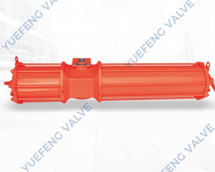
Recent fluid control reports highlight a massive industry shift toward predictive maintenance. Facilities invest heavily in IoT-enabled sensors and smart positioners to monitor pneumatic health in real-time. The goal is to catch anomalies before they cause shutdowns. Yet, despite these high-tech advancements, field data repeatedly confirms a sobering fact. The root cause of most mid-cycle stalls remains remarkably low-tech. It is almost always inadequate air supply. Technology accurately flags the stall, but basic pneumatic physics dictates the fix.
Diagnosing a stall requires a return to the basic formula governing these devices. Force equals Pressure multiplied by Area. The internal surface area of the piston remains constant. Therefore, any drop in incoming compressed air pressure results in a directly proportional drop in mechanical force. If that generated force dips below the required turning torque, the mechanism simply stops moving.
A remarkably common diagnostic error on the factory floor involves confusing static pressure with volumetric flow rate. A technician taps a local pressure gauge, observes a healthy 80 pounds per square inch, and incorrectly rules out the air supply. Static pressure only indicates the potential force available when the air is completely stationary.
Once the actuation cycle initiates, the expanding cylinder chamber requires a specific volume of air to sustain continuous movement. If a hidden restriction exists within the airline, the system may display adequate static pressure at rest. However, it completely lacks the necessary airflow volume to complete the stroke. The moment the internal port opens, the pressure plummets. This starves the valve actuator of kinetic energy and causes a sudden freeze.
Complex industrial pneumatic networks often feature dozens of devices operating simultaneously on a shared main airline. If several high-demand machines happen to cycle at the exact same millisecond, they induce a sudden drop in available air volume across the local grid. This temporary vacuum starves a specific unit of the air it desperately needs. It leads to an unpredictable stall that is notoriously difficult to replicate during isolated testing.
Systematic troubleshooting prevents unnecessary teardowns and inflated maintenance costs. Maintenance personnel can quickly isolate elusive air supply problems by following a logical sequence.
Always begin your investigation at the source. Check the main compressor output gauges to ensure baseline facility requirements are met without excessive fluctuation. Moving closer to the problem zone, verify the local pressure. Most industrial units demand a minimum operating pressure of 60 to 80 pounds per square inch to function reliably. Crucially, you must monitor this gauge during the actual actuation cycle. The pressure must remain stable under load, rather than just checking it while the system is idle.
Air preparation units serve as vital gatekeepers of air quality. They are prime suspects when airflow is restricted. Clogged particulate filters act like a dense wall. They severely throttle airflow volume. Similarly, a ruptured diaphragm inside an air regulator might bottleneck the volume right before it enters the cylinder. Furthermore, improperly calibrated lubricators can inject heavy oil sludge into the lines. This gradually clogs downstream pilot ports over months of operation.
The directional solenoid valve acts as the routing brain. It dictates exactly where the compressed air travels. Should the internal spool become sticky due to microscopic debris, the valve may only open partially. This partial opening chokes the airflow. Utilize the manual override button found on most industrial solenoids to physically bypass the electrical circuit. If the cylinder cycles smoothly at full speed using the override, the mechanical components are perfectly fine. The fault lies entirely within the electrical signal or the solenoid coil.
If the air pressure, volume, air preparation units, and routing pathways are all verified as optimal, the investigation must shift inward. At this stage, the stall is almost certainly driven by internal component fatigue or overwhelming external mechanical resistance.
To streamline your diagnostic process on the factory floor, reference this core troubleshooting matrix:
Symptom Observed | Pneumatic Root Cause | Mechanical Root Cause | Recommended Action |
|---|---|---|---|
Continuous hissing when stationary | Air supply leak at fittings | Internal seal degradation (Blow-by) | Perform soapy water test; replace internal O-rings. |
Sluggish, jerky movement | Restricted CFM at regulator | Lack of lubrication or cylinder scoring | Check FRL flow capacity; inspect cylinder walls for damage. |
Stalls precisely at mid-stroke | Sudden pressure drop in shared line | Valve media buildup or broken return spring | Monitor dynamic pressure; decouple and test bare valve torque. |
Inside the cylinder housing, precise O-rings and heavy-duty piston seals maintain the critical air pressure barrier. Continuous friction and abrasive particulate matter eventually wear these seals flat. When this barrier is compromised, highly pressurized air bypasses the piston head. This failure condition is known as blow-by. The air vents directly out of the opposing exhaust port. Taking the path of least resistance, the unit loses all driving force and stalls.
Occasionally, the pneumatic driving mechanism functions flawlessly, but the bolted process valve has completely seized. Highly viscous process media buildup or severe thermal expansion can cause the required turning torque to spike dramatically. If this new friction threshold exceeds the maximum rated output, the system jams. This mimics a pneumatic failure when the true issue is entirely mechanical.
Once a definitive failure is confirmed, maintenance directors face a critical financial choice. Should they repair the existing unit or replace it entirely? This decision must rely on a rigorous Total Cost of Ownership analysis rather than just the upfront price tag.
Repairs are generally cost-effective for minor peripheral issues. Replacing brittle external tubing or swapping out a burned-out solenoid coil restores functionality quickly. Assuming the internal aluminum cylinder walls remain smooth, a simple bench rebuild is frequently the most logical path forward.
In contrast, total replacement becomes mandatory when irreversible mechanical damage is discovered. Deep gouging score marks on the internal cylinder walls compromise structural integrity. If an aging legacy unit requires constant rebuilding, the compounding cost of maintenance labor will rapidly eclipse the purchase price of brand-new hardware.
When specifying a replacement, selecting industrial-grade hardware is non-negotiable. For instance, upgrading to an AW pneumatic actuator provides definitive engineering advantages that directly prevent future stalls. Consider these critical specifications during your selection process:
Housing Material: Look for extruded aluminum bodies with hard-anodized finishes. This resists harsh environmental corrosion and prevents internal scoring.
Operating Pressure Range: Ensure the unit operates efficiently across a standard 3 to 8 bar range. This accommodates typical plant air fluctuations without stalling.
Mounting Standards: Standardized ISO 5211 and NAMUR mounting pads allow seamless integration with existing valves and solenoid accessories.
Torque Output: Match the torque curve precisely. Spring-return models must provide sufficient end-of-spring torque to guarantee a fail-safe close during emergency power loss.
Preventing mid-cycle stalls requires a calculated combination of proper engineering design and highly disciplined maintenance routines.
Proper sizing is paramount. Never specify equipment based purely on the exact bare-minimum torque of the process valve. Always engineer a generous safety factor. Adding twenty to thirty percent above the published maximum torque comfortably accounts for future media buildup and unexpected friction changes.
Furthermore, air quality management is equally critical. Facilities must utilize clean and dry instrument air. Residual moisture causes insidious internal rust. Microscopic particulate matter acts like sandpaper, aggressively grinding away at internal seals with every single stroke. Transitioning from traditional time-based maintenance to cycle-count maintenance also yields massive benefits. Inspecting components after a specific number of actuations provides a data-driven reflection of true component wear.
Systematic troubleshooting saves facilities immeasurable amounts of time and capital. Always interrogate your air lines before unbolting the equipment.
Most industrial units are explicitly designed to operate efficiently at a regulated air supply pressure between 60 and 120 pounds per square inch. It is imperative to check the manufacturer identification tag. Attempting to operate the unit below its stated minimum pressure threshold will inevitably cause sluggish movement or mid-cycle stalls.
Absolutely. If the solenoid valve is internally clogged with pipe scale, or if the electrical coil is experiencing a severe voltage drop, the internal spool may not shift completely. This heavily restricts the volumetric airflow reaching the main cylinder. It causes the mechanism to move erratically, slow down, or freeze entirely in the middle of its stroke.
The safest and most definitive method is mechanical isolation. Safely relieve all compressed air pressure, lock out the system, and physically decouple the driving unit from the process valve mounting pad. Once separated, manually test the valve stem with a wrench. If the valve is completely seized, the pneumatic mechanism is likely fine. If the bare valve turns easily, the core issue lies within the internal components or the upstream air supply.
Engineers typically apply a safety factor based on the process media. For clean lubricating fluids, a 20 percent markup over the maximum valve torque is sufficient. For dry gases, slurries, or abrasive media, you should apply a 30 to 50 percent safety factor. This ensures the unit has enough reserve kinetic energy to push through unexpected friction spikes without stalling.
Directional sluggishness is almost always caused by an unbalanced airflow restriction. This usually traces back to a clogged exhaust muffler on one side of the solenoid valve, or a faulty unidirectional flow control valve. If the air cannot vent out of the exhausting chamber quickly enough, it creates backpressure that fights the driving piston, slowing it down in that specific direction.
This depends entirely on the specific engineering design of the unit. Many modern high-tier units are factory-lubricated for life using specialized synthetic greases. They require only clean, completely dry instrument air. Introducing externally lubricated air into these specific systems can actually wash away the critical factory grease, accelerating friction and leading to premature seal failure.
When legacy systems reach the end of their usable life, upgrading to robust fluid control networks is the smartest investment. For high-performance solutions engineered to withstand the toughest industrial demands, explore the comprehensive range of pneumatic valve automation systems at GWV Valve. Proper sizing, reliable hardware, and expert support ensure your production lines never experience an unexpected stall again.


